| Product |
| Brand | Schneider Electric |
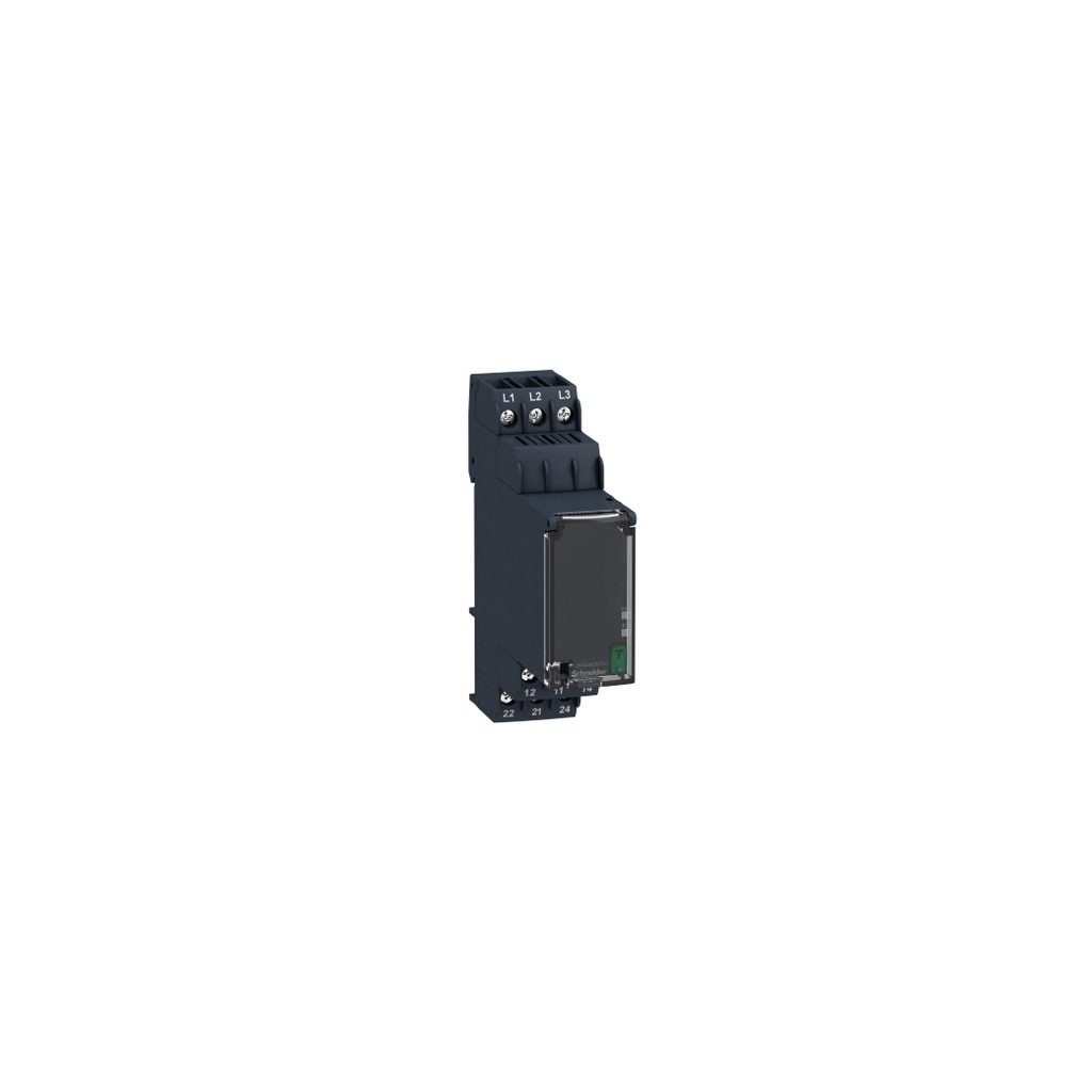
| Part Number / SKU | RMNF22TB30 |
| Category | Relay |
| Main |
| Range of product | Harmony Control Relays |
| Relay type | Control relay |
| Product or component type | NFC control relay |
| Network number of phases | 3 phases |
| Relay name | RMNF22 |
| Relay monitored parameters | Phase sequence
Phase failure detection
Overvoltage detection
Undervoltage detection
Overfrequency and underfrequency
Asymmetry |
| App for product | Ecostruxure Industrial Device (downloadable from Google Play store or Apple Store) |
| Product compatibility | NFC enabled mobile device |
| Time delay type | Adjustable 0.1 s…1 min Tt- time delay upon fault |
| Switching capacity in VA | 2000 VA |
| Complementary |
| NFC operating frequency | 13.56 MHz |
| Maximum RF power transmitted | 0.0002 mW |
| Reset time | 1500 ms at maximum voltage |
| Maximum switching voltage | 250 V AC |
| Minimum switching current | 100 mA at 6 V |
| Maximum switching current | 8 A AC |
| Supply voltage limits | 166.4…576 V AC line to line
96…332.4 V AC line to neutral |
| Power consumption in VA | 4 VA at 480 V AC 60 Hz |
| On-load factor | 100 % |
| supply voltage frequency | 50…60 Hz +/- 10 % |
| Output contacts | 2 C/O |
| Measurement range | 208…480 V AC |
| Setting accuracy of the switching threshold | +/- (1.5 % + 1 V) |
| Setting accuracy of time delay | +/- 3 % for 10 s…60 min time delay range
+/- 300 ms for 0…10 s time delay range |
| Hysteresis | 3 % of fixed for phase failure detection |
| Alarm threshold | 166…576 V adjustable overvoltage and undervoltage detection (line to line)
96…332 V adjustable overvoltage and undervoltage detection (line to neutral)
5…150 V adjustable asymmetry
45…66 Hz adjustable overfrequency or underfrequency |
| Run-up delay at power-up max | 650 ms |
| Maximum measuring cycle | 150 ms measurement cycle as true rms value |
| Threshold adjustment voltage | 2…20 % of Un selected |
| Adjustment of asymmetry threshold | 2…20 % of Un selected |
| Repeat accuracy | +/- 0.5 % for input circuit
+/- 3 % for time delay |
| Setting accuracy of the switching threshold | +/- (1.5 % + 1 V) |
| Measurement error | < 0.05 %/Hz with frequency variation
< 0.05 %/°C with temperature variation |
| Response time | <= 300 ms |
| Insulation resistance | > 100 MOhm at 500 V DC conforming to IEC 60255-27 |
| [Ui] rated insulation voltage | 400 V |
| [Uimp] rated impulse withstand voltage | 4 kV during 1.2/50 µs |
| Dielectric test voltage | 2.5 kV, 1 min AC 50 Hz conforming to IEC 60255-27 |
| Mounting position | Any position |
| Connections – terminals | Screw terminals, 2 x 0.5…2 x 2.5 mm² (AWG 20…AWG 14) solid without cable end
Screw terminals, 2 x 0.5…2 x 1.5 mm² (AWG 20…AWG 16) flexible with cable end
Screw terminals, 1 x 0.5…1 x 3.3 mm² (AWG 20…AWG 12) solid without cable end
Screw terminals, 1 x 0.5…1 x 2.5 mm² (AWG 20…AWG 14) flexible with cable end |
| Tightening torque | 0.6…1 N.m conforming to IEC 60947-1
0.6…1.0 N.m conforming to IEC 60947-1 |
| Housing material | Polycarbonate |
| Local signalling | LED Un: (steady), green for power ON
LED R1: (steady), amber for relay energised
LED R1: (blinking), amber for timing in progress
LED R2: (steady), amber for relay energised
LED R2: (blinking), amber for timing in progress
LED PL: (steady), red for alarm phase failure triggered
LED PS: (blinking), red for alarm phase sequence failure triggered
LED UV: (steady), red for alarm undervoltage failure triggered
LED OV: (blinking), red for alarm overvoltage failure triggered
LED UF: (steady), red for alarm underfrequency failure triggered
LED OF: (blinking), red for alarm overfrequency failure triggered
LED ASYM: (steady), red for alarm asymmentry failure triggered |
| Mounting support | 35 mm DIN rail conforming to IEC 60715 |
| Electrical durability | 100000 cycles |
| Mechanical durability | 10000000 cycles |
| Utilisation category | AC-15 conforming to IEC 60947-5-1
DC-13 conforming to IEC 60947-5-1
AC-1 conforming to IEC 60947-4-1
DC-1 conforming to IEC 60947-4-1 |
| [Ith] conventional free air thermal current | 8 A |
| [Un] rated nominal voltage | 208…480 V AC 50/60 Hz, non self-powered
120…277 V AC 50/60 Hz, non self-powered |
| Operating system | Androidversion >= V7.0
IOSversion >= V14.5 |
| Contacts material | Cadmium free |
| Control type | Without test button |
| Width | 22.5 mm |
| Height | 90 mm |
| Depth | 99 mm |
| Contacts type and composition | 2 C/O |
| Product weight | 0.125 kg |
| Environment |
| Immunity to microbreaks | 10 ms |
| Electromagnetic compatibility | Voltage dips and interruptions immunity test – test level: 70 % (25/30 cycles) conforming to IEC 61000-4-11
Electrostatic discharge – test level: 6 kV level 3 (contact discharge) conforming to IEC 61000-4-2
Radiated radio-frequency electromagnetic field immunity test – test level: 10 V/m level 3 conforming to IEC 61000-4-3
Immunity for industrial environments conforming to IEC 61000-6-2
1 MHz damped oscillating wave – test level: 2.5 kV CM, 1 kV DM criteria B conforming to IEC 61000-4-18
Voltage dips and interruptions immunity test – test level: 0 % (0.5…25 cycles) conforming to IEC 61000-4-11
Magnetic field at power frequency – test level: 30 A/m (continuous)-300 A/m (1-3 s) level 4 conforming to IEC 61000-4-8
Surge immunity test – test level: 2 kV level 4 (differential mode) conforming to IEC 61000-4-5
Immunity for residential, commercial and light-industrial environments conforming to IEC 61000-6-1
Voltage dips and interruptions immunity test – test level: 40 % (10/12 cycles) conforming to IEC 61000-4-11
Voltage interruptions – test level: 0 % criteria C (250/300 cycles) conforming to IEC 61000-4-29
Electrical fast transient/burst immunity test – test level: 4 kV criteria B (direct) conforming to IEC 61000-4-4
Emission standard for industrial environments conforming to IEC 61000-6-4
Surge immunity test – test level: 4 kV level 4 (common mode) conforming to IEC 61000-4-5
Electrostatic discharge – test level: 8 kV level 3 (air discharge) conforming to IEC 61000-4-2
Conducted RF disturbances level 3 conforming to IEC 61000-4-6 |
| Standards | IEC 60255-1 |
| Product certifications | CE
UL
CSA
CCC
EAC
RCM |
| Directives | 2014/30/EU – electromagnetic compatibility
2014/35/EU – low voltage directive
2014/53/EU – radio equipment directive |
| Ambient air temperature for storage | -40…70 °C |
| Ambient air temperature for operation | -20…60 °C |
| Relative humidity | 93…97 % at 25…55 °C conforming to IEC 60068-2-30 |
| Vibration resistance | 0.075 mm (f= 10…58.1 Hz) not in operation conforming to IEC 60068-2-6
1 gn (f= 58.1…150 Hz) not in operation conforming to IEC 60068-2-6
0.035 mm (f= 10…58.1 Hz) in operation conforming to IEC 60068-2-6
0.5 gn (f= 58.1…150 Hz) in operation conforming to IEC 60068-2-6 |
| Shock resistance | 15 gn (duration = 11 ms) for not in operation conforming to IEC 60068-2-27
5 gn (duration = 11 ms) for in operation conforming to IEC 60068-2-27 |
| IP degree of protection | IP20 (terminals) conforming to IEC 60529
IP40 (housing) conforming to IEC 60529
IP40 (front panel) conforming to IEC 60529 |
| Pollution degree | 3 conforming to IEC 60664-1
3 conforming to UL 508 |
| Overvoltage category | III conforming to IEC 60664-1
III conforming to UL 508 |
| Packing Units |
| Unit Type of Package 1 | PCE |
| Number of Units in Package 1 | 1 |
| Package 1 Height | 3.000 cm |
| Package 1 Width | 10.000 cm |
| Package 1 Length | 10.800 cm |
| Package 1 Weight | 138.000 g |
| Unit Type of Package 2 | S02 |
| Number of Units in Package 2 | 36 |
| Package 2 Height | 15.000 cm |
| Package 2 Width | 30.000 cm |
| Package 2 Length | 40.000 cm |
| Package 2 Weight | 5.578 kg |
| Unit Type of Package 3 | P06 |
| Number of Units in Package 3 | 576 |
| Package 3 Height | 75.000 cm |
| Package 3 Width | 60.000 cm |
| Package 3 Length | 80.000 cm |
| Package 3 Weight | 98.000 kg |
| Contractual warranty |
| Warranty (in months) | 18 |