| Product |
| Brand | Schneider Electric |
| Part Number / SKU | ATV930C25N4C |
| Category | Variable Frequency Drive (VFD) |
| Main |
| Range of product | Altivar Process ATV900 |
| Product specific application | Process for industrial |
| Product or component type | Variable speed drive |
| Variant | Standard version
Without braking chopper |
| Device application | Industrial application |
| Product destination | Synchronous motors
Asynchronous motors |
| Network number of phases | 3 phases |
| Mounting mode | Wall mount |
| Continuous output current | 481 A at 2.5 kHz for normal duty
387 A at 2.5 kHz for heavy duty |
| Communication port protocol | Modbus serial
EtherNet/IP
Modbus TCP |
| option module | Slot A: communication module for Profibus DP V1
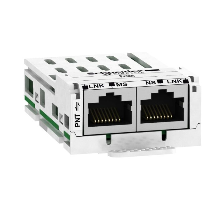
Slot A: communication module for PROFINET
Slot A: communication module for DeviceNet
Slot A: communication module for EtherCAT
Slot A: communication module for CANopen daisy chain RJ45
Slot A: communication module for CANopen SUB-D 9
Slot A: communication module for CANopen screw terminals
Slot A/slot B/slot C: digital and analog I/O extension module
Slot A/slot B/slot C: output relay extension module
Slot B: 5/12 V digital encoder interface module
Slot B: analog encoder interface module
Slot B: resolver encoder interface module
communication module for Ethernet Powerlink |
| [Us] rated supply voltage | 380…480 V – 15…10 % |
| [Us] rated supply voltage | 380…480 V |
| Relative symmetric mains voltage tolerance | 10 % |
| Relative symmetric network frequency tolerance | 5 % |
| nominal output current | 481.0 A |
| Motor power kW | 250.0 kW for normal duty
200.0 kW for heavy duty |
| EMC filter | Integrated
With EMC plate option |
| IP degree of protection | IP21 |
| Degree of protection | UL type 1 |
| Complementary |
| Electrical connection | Control: screw terminal 0.5…1.5 mm²/AWG 20…AWG 16
Line side: screw terminal 4 x 185 mm²/3 x 350 kcmil
Motor: screw terminal 4 x 185 mm²/3 x 350 kcmil
DC bus: screw terminal 4 x 185 mm²/3 x 350 kcmil |
| Transmission rate | 10/100 Mbit/s for Ethernet IP/Modbus TCP
4.8, 9.6, 19.2, 38.4 kbit/s for Modbus serial |
| Exchange mode | Half duplex, full duplex, autonegotiation Ethernet IP/Modbus TCP |
| Data format | 8 bits, configurable odd, even or no parity for Modbus serial |
| Type of polarization | No impedance for Modbus serial |
| Number of addresses | 1…247 for Modbus serial |
| Supply | External supply for digital inputs: 24 V DC (19…30 V), <1.25 mA, protection type: overload and short-circuit protection
Internal supply for reference potentiometer (1 to 10 kOhm): 10.5 V DC +/- 5 %, <10 mA, protection type: overload and short-circuit protection
Internal supply for digital inputs and STO: 24 V DC (21…27 V), <200 mA, protection type: overload and short-circuit protection |
| Local signalling | Local diagnostic: 3 LED (mono/dual colour)
Presence of voltage: 1 LED (red)
Embedded communication status: 3 LED (dual colour)
Communication module status: 4 LED (dual colour) |
| Input compatibility | DI1…DI8: discrete input level 1 PLC conforming to IEC 61131-2
DI7, DI8: pulse input level 1 PLC conforming to IEC 65A-68
STOA, STOB: discrete input level 1 PLC conforming to IEC 61131-2 |
| Discrete input logic | Positive logic (source) (DI1…DI8), < 5 V (state 0), > 11 V (state 1)
Negative logic (sink) (DI1…DI8), > 16 V (state 0), < 10 V (state 1)
Positive logic (source) (DI7, DI8), < 0.6 V (state 0), > 2.5 V (state 1)
Positive logic (source) (STOA, STOB), < 5 V (state 0), > 11 V (state 1) |
| Sampling duration | 2 ms +/- 0.5 ms (DI1…DI8) – discrete input
5 ms +/- 1 ms (DI7, DI8) – pulse input
1 ms +/- 1 ms (AI1, AI2, AI3) – analog input
5 ms +/- 1 ms (AQ1, AQ2) – analog output |
| Accuracy | +/- 0.6 % AI1, AI2, AI3 for a temperature variation 60 °C analog input
+/- 1 % AQ1, AQ2 for a temperature variation 60 °C analog output |
| Linearity error | AI1, AI2, AI3: +/- 0.15 % of maximum value for analog input
AQ1, AQ2: +/- 0.2 % for analog output |
| Refresh time | Relay output (R1, R2, R3): 5 ms (+/- 0.5 ms) |
| Isolation | Between power and control terminals |
| Discrete input number | 10 |
| Discrete input type | DI1…DI8 programmable, 24 V DC (<= 30 V), impedance: 3.5 kOhm
DI7, DI8 programmable as pulse input: 0…30 kHz, 24 V DC (<= 30 V)
STOA, STOB safe torque off, 24 V DC (<= 30 V), impedance: > 2.2 kOhm |
| Discrete output number | 2 |
| Discrete output type | Logic output DQ+ 0…1 kHz <= 30 V DC 100 mA
Programmable as pulse output DQ+ 0…30 kHz <= 30 V DC 20 mA
Logic output DQ- 0…1 kHz <= 30 V DC 100 mA |
| Analogue input number | 3 |
| Analogue input type | AI1, AI2, AI3 software-configurable voltage: 0…10 V DC, impedance: 30 kOhm, resolution 12 bits
AI1, AI2, AI3 software-configurable current: 0…20 mA/4…20 mA, impedance: 250 Ohm, resolution 12 bits |
| Analogue output number | 2 |
| Analogue output type | Software-configurable voltage AQ1, AQ2: 0…10 V DC impedance 470 Ohm, resolution 10 bits
Software-configurable current AQ1, AQ2: 0…20 mA impedance 500 Ohm, resolution 10 bits |
| Relay output number | 3 |
| Relay output type | Configurable relay logic R1: fault relay NO/NC electrical durability 100000 cycles
Configurable relay logic R2: sequence relay NO electrical durability 1000000 cycles
Configurable relay logic R3: sequence relay NO electrical durability 1000000 cycles |
| Maximum switching current | Relay output R1 on resistive load, cos phi = 1: 3 A at 250 V AC
Relay output R1 on resistive load, cos phi = 1: 3 A at 30 V DC
Relay output R1 on inductive load, cos phi = 0.4 and L/R = 7 ms: 2 A at 250 V AC
Relay output R1 on inductive load, cos phi = 0.4 and L/R = 7 ms: 2 A at 30 V DC
Relay output R2, R3 on resistive load, cos phi = 1: 5 A at 250 V AC
Relay output R2, R3 on resistive load, cos phi = 1: 5 A at 30 V DC
Relay output R2, R3 on inductive load, cos phi = 0.4 and L/R = 7 ms: 2 A at 250 V AC
Relay output R2, R3 on inductive load, cos phi = 0.4 and L/R = 7 ms: 2 A at 30 V DC |
| Minimum switching current | Relay output R1, R2, R3: 5 mA at 24 V DC |
| Discrete input logic | 16 preset speeds |
| Physical interface | Ethernet
2-wire RS 485 |
| Connector type | 2 RJ45
1 RJ45 |
| Method of access | Slave Modbus TCP |
| Transmission rate | 10, 100 Mbits
4.8 kbps
9600 bit/s
19200 bit/s |
| Transmission frame | RTU |
| Number of addresses | 1…247 |
| Data format | 8 bits, configurable odd, even or no parity |
| Type of polarization | No impedance |
| 4 quadrant operation possible | False |
| Asynchronous motor control profile | Variable torque standard
Constant torque standard
Optimized torque mode |
| Synchronous motor control profile | Permanent magnet motor
Synchronous reluctance motor |
| Maximum output frequency | 599 Hz |
| Acceleration and deceleration ramps | Linear adjustable separately from 0.01…9999 s |
| Motor slip compensation | Adjustable
Can be suppressed
Automatic whatever the load
Not available in permanent magnet motor law |
| Switching frequency | 1…8 kHz adjustable
2.5…8 kHz with derating factor |
| Nominal switching frequency | 2.5 kHz |
| Braking to standstill | By DC injection |
| Brake chopper integrated | False |
| Line current | 451.0 A at 380 V (normal duty)
365.0 A at 380 V (heavy duty)
366.0 A at 480 V (normal duty)
301.0 A at 480 V (heavy duty) |
| Maximum input current | 451.0 A |
| Maximum output voltage | 480.0 V |
| Apparent power | 279 kVA at 480 V (normal duty)
229 kVA at 480 V (heavy duty) |
| Maximum transient current | 577 A during 60 s (normal duty)
581 A during 60 s (heavy duty) |
| Network frequency | 50…60 Hz |
| Prospective line Isc | 50 kA |
| Base load current at high overload | 387.0 A |
| Base load current at low overload | 481.0 A |
| Power dissipation in W | Forced convection: 5773 W at 380 V, switching frequency 2.5 kHz
Natural convection: 606 W at 380 V, switching frequency 2.5 kHz |
| With safety function Safely Limited Speed (SLS) | True |
| With safety function Safe brake management (SBC/SBT) | True |
| With safety function Safe Operating Stop (SOS) | False |
| With safety function Safe Position (SP) | False |
| With safety function Safe programmable logic | False |
| With safety function Safe Speed Monitor (SSM) | False |
| With safety function Safe Stop 1 (SS1) | True |
| With sft fct Safe Stop 2 (SS2) | False |
| With safety function Safe torque off (STO) | True |
| With safety function Safely Limited Position (SLP) | False |
| With safety function Safe Direction (SDI) | False |
| Protection type | Thermal protection: motor
Safe torque off: motor
Motor phase break: motor
Thermal protection: drive
Safe torque off: drive
Overheating: drive
Overcurrent between output phases and earth: drive
Overload of output voltage: drive
Short-circuit protection: drive
Motor phase break: drive
Overvoltages on the DC bus: drive
Line supply overvoltage: drive
Line supply undervoltage: drive
Line supply phase loss: drive
Overspeed: drive
Break on the control circuit: drive |
| Quantity per set | 1 |
| Width | 598 mm |
| Height | 1195 mm |
| Depth | 380 mm |
| Product weight | 203 kg |
| Environment |
| Insulation resistance | > 1 MOhm 500 V DC for 1 minute to earth |
| Noise level | 76 dB conforming to 86/188/EEC |
| Vibration resistance | 1.5 mm peak to peak (f= 2…13 Hz) conforming to IEC 60068-2-6
1 gn (f= 13…200 Hz) conforming to IEC 60068-2-6 |
| Shock resistance | 15 gn for 11 ms conforming to IEC 60068-2-27 |
| Environmental characteristic | Chemical pollution resistance class 3C2 conforming to IEC 60721-3-3
Dust pollution resistance class 3S2 conforming to IEC 60721-3-3 |
| Relative humidity | 5…95 % without condensation conforming to IEC 60068-2-3 |
| Ambient air temperature for operation | -10…40 °C (without derating)
40…60 °C (with derating factor) |
| Operating altitude | <= 1000 m without derating
1000…3000 m with current derating 1 % per 100 m |
| Operating position | Vertical +/- 10 degree |
| Product certifications | UL
CSA
TÜV |
| Marking | CE |
| Standards | UL 508C
IEC 61800-3
IEC 61800-5-1
IEC 61000-3-12
IEC 60721-3
IEC 61508
IEC 13849-1 |
| Maximum THDI | <48 % full load conforming to IEC 61000-3-12 |
| Assembly style | Enclosed |
| Electromagnetic compatibility | Electrostatic discharge immunity test level 3 conforming to IEC 61000-4-2
Radiated radio-frequency electromagnetic field immunity test level 3 conforming to IEC 61000-4-3
Electrical fast transient/burst immunity test level 4 conforming to IEC 61000-4-4
1.2/50 µs – 8/20 µs surge immunity test level 3 conforming to IEC 61000-4-5
Conducted radio-frequency immunity test level 3 conforming to IEC 61000-4-6 |
| Environmental class (during operation) | Class 3C3 according to IEC 60721-3-3
Class 3S3 according to IEC 60721-3-3 |
| Maximum acceleration under shock impact (during operation) | 150 m/s² at 11 ms |
| Maximum acceleration under vibrational stress (during operation) | 10 m/s² at 13…200 Hz |
| Maximum deflection under vibratory load (during operation) | 1.5 mm at 2…13 Hz |
| Permitted relative humidity (during operation) | Class 3K5 according to EN 60721-3 |
| Volume of cooling air | 1260 m3/h |
| Overvoltage category | III |
| Regulation loop | Adjustable PID regulator |
| Noise level | 76 dB |
| Pollution degree | 2 |
| Ambient air transport temperature | -25…70 °C |
| Ambient air temperature for storage | -25…70 °C |
| Packing Units |
| Unit Type of Package 1 | PCE |
| Number of Units in Package 1 | 1 |
| Package 1 Height | 64.000 cm |
| Package 1 Width | 77.000 cm |
| Package 1 Length | 140.000 cm |
| Package 1 Weight | 252.000 kg |
| Contractual warranty |
| Warranty (in months) | 18 |