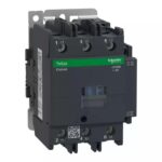
LC1D95F5 | POWER CONTACT D MODEL 95A 3P COIL:110VAC – Schneider Electric
₹45,660.00 Original price was: ₹45,660.00.₹20,547.00Current price is: ₹20,547.00. Excl. GST
Dispatch By : 7 Weeks
Order protection
Buy with complete confidence.
We back each order with genuine supply, on-time dispatch and GST or commercial invoicing as required.
Additional Addons/Accessories
LA4DT4U | ELECTRONIC TIMER DELAY ON 25- 500 SEC – Schneider Electric
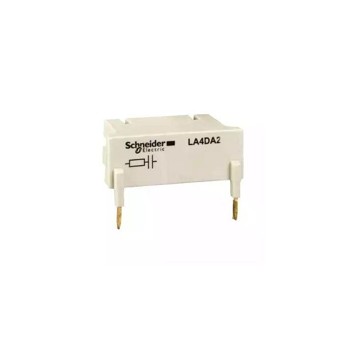
LA4DA2U | TeSys D – suppressor module – RC circuit – 110…240 V AC – Schneider Electric
LADN20 | Auxiliary contact block, TeSys D, 2NO, front mounting, screw clamp terminals – Schneider Electric
LADN22 | Auxiliary contact block, TeSys D, 2NO + 2NC, front mounting, screw clamp terminals – Schneider Electric
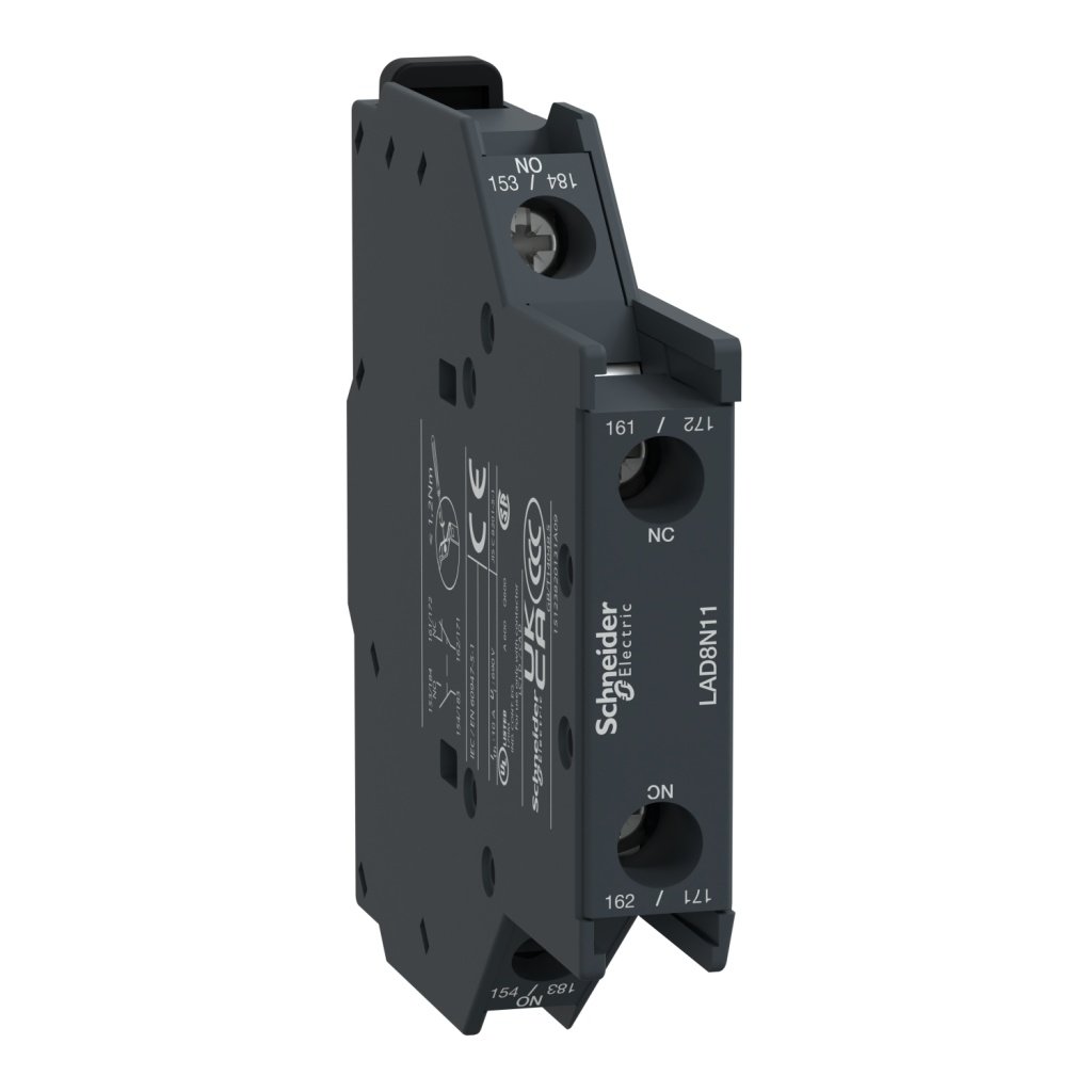
LAD8N11 | Auxiliary contact block, TeSys D, 1NO + 1NC, side mounting, screw clamp terminals – Schneider Electric
LADN31 | Auxiliary contact block, TeSys D, 3NO + 1NC, front mounting, screw clamp terminals – Schneider Electric
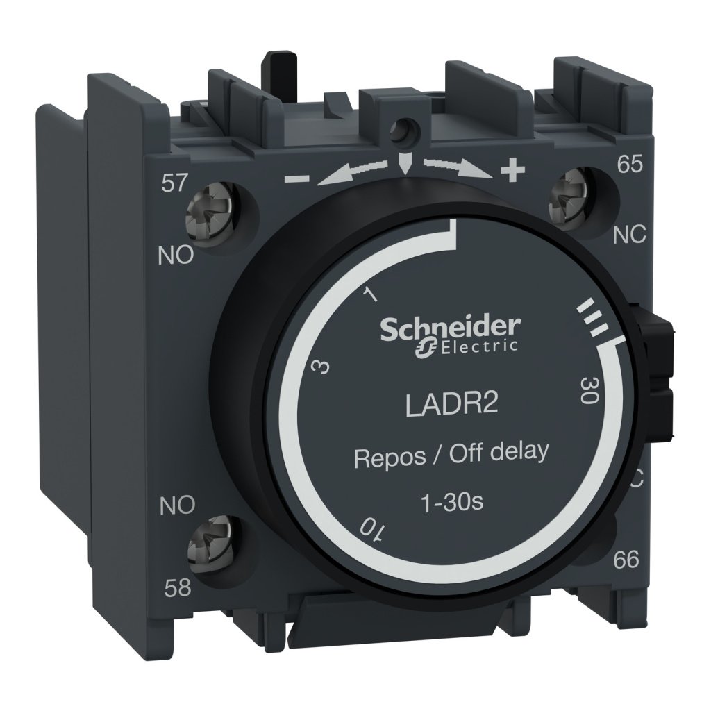
LADR2 | TeSys D – time delay auxiliary contact block – 1 NO + 1 NC screw clamp terminals – Schneider Electric
LA4DA2G | SUPPRESSOR BLOCK – Schneider Electric
LADN11 | Auxiliary contact block, TeSys D, 1NO + 1NC, front mounting, screw clamp terminals – Schneider Electric
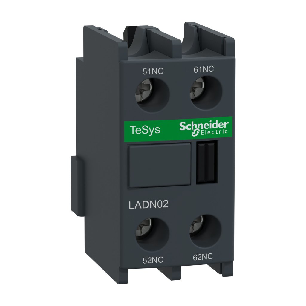
LADN02 | Auxiliary contact block, TeSys D, 2NC, front mounting, screw clamp terminals – Schneider Electric
LX1D6F5 | COIL OLD D40-D95 110VAC 50HZ – Schneider Electric
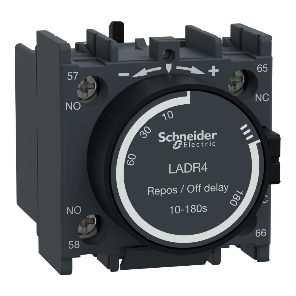
LADR4 | TeSys D – time delay auxiliary contact block – 1 NO + 1 NC screw clamp terminals – Schneider Electric
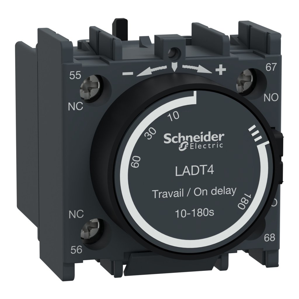
LADT4 | TeSys D – time delay auxiliary contact block – 1 NO + 1 NC screw clamp terminals – Schneider Electric
LA4DWB | DC SUPPLY BLOCK – Schneider Electric
LADT2 | TeSys D – time delay auxiliary contact block – 1 NO + 1 NC screw clamp terminals – Schneider Electric
LA4DE2U | VARISTOR SUPPRES 110-250VAC FOR D80-D115 – Schneider Electric
LADN40 | Auxiliary contact block, TeSys D, 4NO, front mounting, screw clamp terminals – Schneider Electric
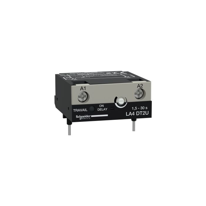
LA4DT2U | ELECTRONIC TIMER DELAY ON 1.5 – 30SEC – Schneider Electric
LADN13 | Auxiliary contact block, TeSys D, 1NO + 3NC, front mounting, screw clamp terminals – Schneider Electric
LAD8N02 | Auxiliary contact block, TeSys D, 2NC, side mounting, screw clamp terminals – Schneider Electric
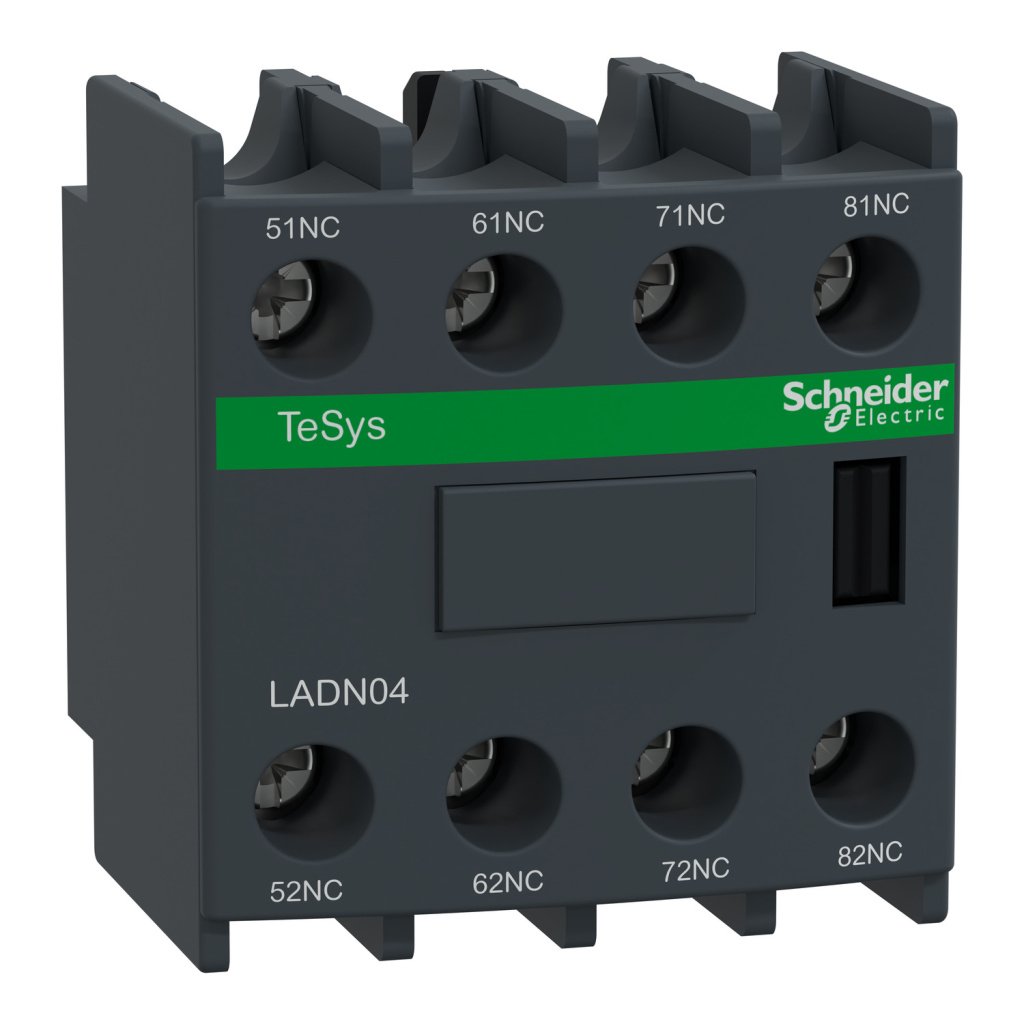
LADN04 | Auxiliary contact block, TeSys D, 4NC, front mounting, screw clamp terminals – Schneider Electric
LADT0 | TeSys D – time delay auxiliary contact block – 1 NO + 1 NC screw clamp terminals – Schneider Electric
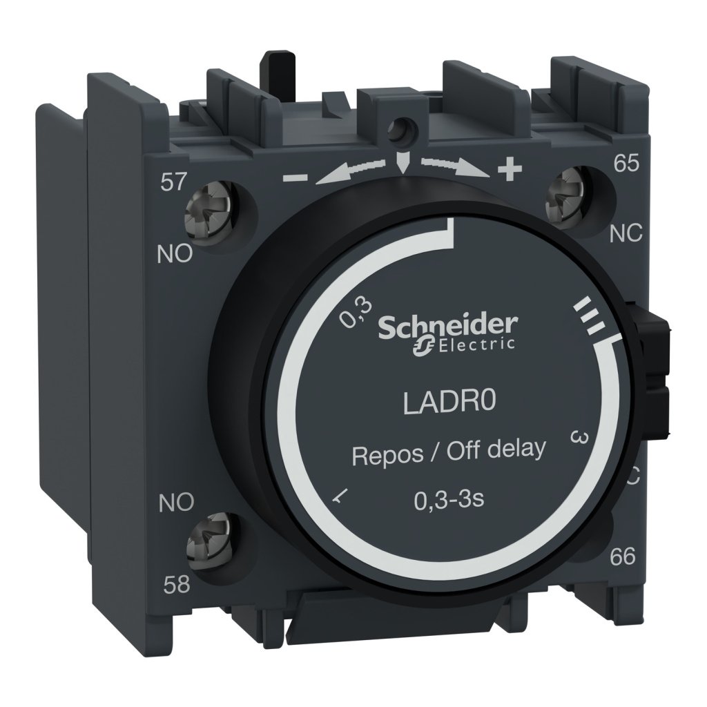
LADR0 | TeSys D – time delay auxiliary contact block – 1 NO + 1 NC screw clamp terminals – Schneider Electric
LA4DT0U | ELECTRONIC TIMER DELAY ON 0.1 – 2SEC – Schneider Electric
LA4DFB | INTERFACE MODULE RELAY 24VDC – Schneider Electric
LADS2 | TeSys D – time delay auxiliary contact block – 1 NO + 1 NC screw clamp terminals – Schneider Electric
LAD8N20 | Auxiliary contact block, TeSys D, 2NO, side mounting, screw clamp terminals – Schneider Electric
Looking for the LC1D95F5 | POWER CONTACT D MODEL 95A 3P COIL:110VAC? This genuine Schneider Electric electrical component from the TeSys range is built for industrial, commercial, and infrastructure applications, combining proven reliability with full compliance to applicable IEC/IS standards. Key ratings include 95 A, Power circuit: <= 690 V AC 25...400 Hz, 3P. Order part number LC1D95F5 from myelectric.in — a trusted Schneider Electric supplier offering competitive pricing, GST billing, and shipping across India and overseas.
📋 Technical Specifications
| Product | |
| Brand | Schneider Electric |
| Part Number / SKU | LC1D95F5 |
| Category | Electrical Component |
| Main | |
| Range | TeSys |
| Range of product | TeSys Deca |
| Product or component type | Contactor |
| Device short name | LC1D |
| Contactor application | Resistive load Motor control |
| Utilisation category | AC-3 AC-3e AC-4 AC-1 |
| Poles description | 3P |
| [Ue] rated operational voltage | Power circuit: <= 690 V AC 25…400 Hz |
| [Ie] rated operational current | 95 A (at <60 °C) at <= 440 V AC-3 for power circuit 125 A (at <60 °C) at <= 1000 V AC-1 for power circuit 95 A (at <60 °C) at <= 440 V AC-3e for power circuit |
| [Uc] control circuit voltage | 110 V AC 50 Hz |
| Complementary | |
| Motor power kW | 25 kW at 220…230 V AC 50 Hz (AC-3) 45 kW at 380…400 V AC 50 Hz (AC-3) 45 kW at 415…440 V AC 50 Hz (AC-3) 55 kW at 500 V AC 50 Hz (AC-3) 45 kW at 660…690 V AC 50 Hz (AC-3) 15 kW at 400 V AC 50 Hz (AC-4) 25 kW at 220…230 V AC 50 Hz (AC-3e) 45 kW at 380…400 V AC 50 Hz (AC-3e) 45 kW at 415…440 V AC 50 Hz (AC-3e) 55 kW at 500 V AC 50 Hz (AC-3e) 45 kW at 660…690 V AC 50 Hz (AC-3e) |
| Motor power hp | 7.5 hp at 120 V AC 60 Hz for 1 phase motors 15 hp at 230/240 V AC 60 Hz for 1 phase motors 30 hp at 200/208 V AC 60 Hz for 3 phases motors 30 hp at 230/240 V AC 60 Hz for 3 phases motors 60 hp at 460/480 V AC 60 Hz for 3 phases motors 60 hp at 575/600 V AC 60 Hz for 3 phases motors |
| Compatibility code | LC1D |
| Pole contact composition | 3 NO |
| Protective cover | With |
| [Ith] conventional free air thermal current | 10 A (at 60 °C) for signalling circuit 125 A (at 60 °C) for power circuit |
| Irms rated making capacity | 1100 A at 440 V AC for power circuit conforming to IEC 60947 140 A AC for signalling circuit conforming to IEC 60947-5-1 250 A DC for signalling circuit conforming to IEC 60947-5-1 |
| Rated breaking capacity | 1100 A at 440 V for power circuit conforming to IEC 60947 |
| [Icw] rated short-time withstand current | 1100 A 40 °C – 1 s for power circuit 800 A 40 °C – 10 s for power circuit 400 A 40 °C – 1 min for power circuit 135 A 40 °C – 10 min for power circuit 140 A – 100 ms for signalling circuit 120 A – 500 ms for signalling circuit 100 A – 1 s for signalling circuit |
| Associated fuse rating | 10 A gG for signalling circuit conforming to IEC 60947-5-1 200 A gG at <= 690 V coordination type 1 for power circuit 160 A gG at <= 690 V coordination type 2 for power circuit |
| Average impedance | 0.8 mOhm – Ith 125 A 50 Hz for power circuit |
| Power dissipation per pole | 12.5 W AC-1 7.2 W AC-3 7.2 W AC-3e |
| [Ui] rated insulation voltage | Power circuit: 1000 V conforming to IEC 60947-4-1 Power circuit: 600 V CSA certified Power circuit: 600 V UL certified Signalling circuit: 690 V conforming to IEC 60947-1 Signalling circuit: 600 V CSA certified Signalling circuit: 600 V UL certified |
| Overvoltage category | III |
| Pollution degree | 3 |
| [Uimp] rated impulse withstand voltage | 8 kV conforming to IEC 60947 |
| Safety reliability level | B10d = 1.3 Mcycles contactor with nominal load conforming to EN/ISO 13849-1 B10d = 20 Mcycles contactor with mechanical load conforming to EN/ISO 13849-1 |
| Mechanical durability | 10 Mcycles |
| Electrical durability | 1.2 Mcycles 95 A AC-3 1.3 Mcycles 125 A AC-1 1.2 Mcycles 95 A AC-3e |
| Control circuit type | AC at 50 Hz |
| Coil technology | Without built-in suppressor module |
| Control circuit voltage limits | 0.3…0.6 Uc (-40…70 °C):drop-out AC 50 Hz 0.85…1.1 Uc (-40…55 °C):operational AC 50 Hz 1…1.1 Uc (55…70 °C):operational AC 50 Hz |
| Inrush power in VA | 200 VA 50 Hz cos phi 0.75 (at 20 °C) |
| Hold-in power consumption in VA | 20 VA 50 Hz cos phi 0.3 (at 20 °C) |
| Heat dissipation | 6…10 W at 50 Hz |
| Operating time | 20…35 ms closing 6…20 ms opening |
| Maximum operating rate | 3600 cyc/h at 60 °C |
| Connections – terminals | Control circuit: screw clamp terminals 2 1…2.5 mm² – cable stiffness: flexible with cable end Control circuit: screw clamp terminals 1 1…2.5 mm² – cable stiffness: flexible with cable end Control circuit: screw clamp terminals 1 1…4 mm² – cable stiffness: flexible without cable end Control circuit: screw clamp terminals 2 1…4 mm² – cable stiffness: flexible without cable end Control circuit: screw clamp terminals 1 1…4 mm² – cable stiffness: solid without cable end Control circuit: screw clamp terminals 2 1…4 mm² – cable stiffness: solid without cable end Power circuit: connector 1 4…50 mm² – cable stiffness: flexible without cable end Power circuit: connector 2 4…25 mm² – cable stiffness: flexible without cable end Power circuit: connector 1 4…50 mm² – cable stiffness: flexible with cable end Power circuit: connector 2 4…16 mm² – cable stiffness: flexible with cable end Power circuit: connector 1 4…50 mm² – cable stiffness: solid without cable end Power circuit: connector 2 4…25 mm² – cable stiffness: solid without cable end |
| Tightening torque | Control circuit: 1.2 N.m – on screw clamp terminals – with screwdriver flat Ø 6 mm Control circuit: 1.2 N.m – on screw clamp terminals – with screwdriver Philips No 2 Power circuit: 12 N.m – on connector – with screwdriver flat Ø 6 to Ø 8 mm Power circuit: 12 N.m – on connector hexagonal screw head 4 mm Control circuit: 1.2 N.m – on screw clamp terminals – with screwdriver pozidriv No 2 |
| Auxiliary contact composition | 1 NO + 1 NC |
| Auxiliary contacts type | type mechanically linked 1 NO + 1 NC conforming to IEC 60947-5-1 type mirror contact 1 NC conforming to IEC 60947-4-1 |
| Signalling circuit frequency | 25…400 Hz |
| Minimum switching voltage | 17 V for signalling circuit |
| Minimum switching current | 5 mA for signalling circuit |
| Insulation resistance | > 10 MOhm for signalling circuit |
| Non-overlap time | 1.5 ms on de-energisation between NC and NO contact 1.5 ms on energisation between NC and NO contact |
| Mounting support | Plate Rail |
| Environment | |
| Standards | EN 60947-4-1 EN 60947-5-1 IEC 60947-4-1 IEC 60947-5-1 CSA C22.2 No 14 UL 60947-4-1 IEC 60335-2-40:Annex JJ UL 60335-2-40:Annex JJ IEC 60335-1:Clause 30.2 |
| Product certifications | CCC UL CB Scheme CSA CE UKCA Marine EAC |
| IP degree of protection | IP20 front face conforming to IEC 60529 |
| Protective treatment | TH conforming to IEC 60068-2-30 |
| Climatic withstand | conforming to IACS E10 exposure to damp heat |
| Permissible ambient air temperature around the device | -40…60 °C 60…70 °C with derating |
| Operating altitude | 0…3000 m |
| Fire resistance | 850 °C conforming to IEC 60695-2-1 |
| Flame retardance | V1 conforming to UL 94 |
| Mechanical robustness | Vibrations contactor open (2 Gn, 5…300 Hz) Shocks contactor open (8 Gn for 11 ms) Vibrations contactor closed (3 Gn, 5…300 Hz) Shocks contactor closed (10 Gn for 11 ms) |
| Height | 127 mm |
| Width | 85 mm |
| Depth | 130 mm |
| Product weight | 1.61 kg |
| Packing Units | |
| Unit Type of Package 1 | PCE |
| Number of Units in Package 1 | 1 |
| Package 1 Height | 10.0 cm |
| Package 1 Width | 13.5 cm |
| Package 1 Length | 14.0 cm |
| Package 1 Weight | 1.559 kg |
| Unit Type of Package 2 | S02 |
| Number of Units in Package 2 | 5 |
| Package 2 Height | 15.0 cm |
| Package 2 Width | 30.0 cm |
| Package 2 Length | 40.0 cm |
| Package 2 Weight | 8.193 kg |
| Contractual warranty | |
| Warranty (in months) | 18 |
⚡ Key Features
- 95 A current rating — confirmed from product specifications; size wiring and terminals to match or exceed this value.
- 110V AC coil or control supply voltage — directly compatible with standard panel control circuits.
- Manufactured to IS/IEC 60947, IS 8828 (MCBs), IS 13947, IEC 61439 (DBs) — complies with Indian BIS and IEC international safety standards.
- BIS certified, CE marked, RoHS compliant — meets Indian regulatory requirements for use in government, commercial, and industrial electrical installations.
- Genuine authorised Schneider Electric product — sourced directly from the official distribution network with full manufacturer traceability and warranty.
- GST invoice provided for India orders — valid for corporate procurement, government project orders, and public tender supply via myelectric.in.
- Worldwide export available — UAE, Singapore, UK, USA, Sri Lanka & more. Contact +91 94814 00316 for bulk pricing and international shipping.
🔗 Compatible Products & Accessories
The following genuine accessories and compatible devices are designed to work with this product. Contact myelectric.in for pricing and availability:
❓ Frequently Asked Questions
Q: What is the significance of the 95 A rating on the LC1D95F5?
A: The 95 A rating is the device’s maximum continuous current carrying capacity under specified conditions (typically 40°C ambient). For circuit design, use 80% of this value as the design current to allow for derating due to grouping, temperature, and future load growth.
Q: The LC1D95F5 has a coil voltage of 110V AC — what control supply is needed?
A: This Schneider Electric device requires a 110V AC control supply connected to the coil terminals (A1 and A2). For AC coils, ensure the control circuit voltage is stable — voltage drops below 85% of rated coil voltage can cause chatter and coil overheating. Always fit a surge suppressor across the coil when switching with a PLC or solid-state relay.


