| Product |
| Brand | Schneider Electric |
| Part Number / SKU | RE22R2MMW |
| Category | Relay |
| Main |
| Range of product | Harmony Timer Relays |
| Discrete output type | Relay |
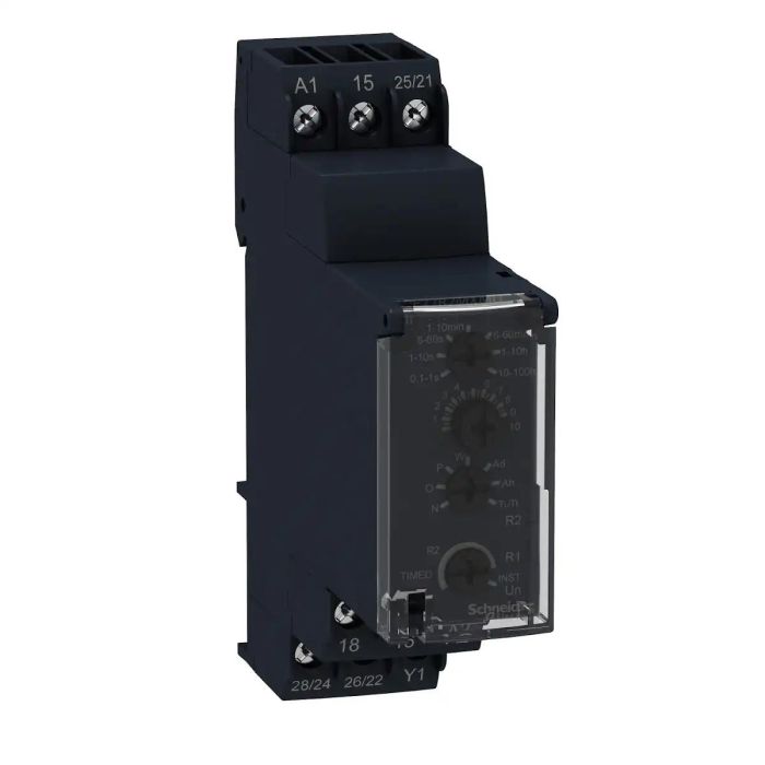
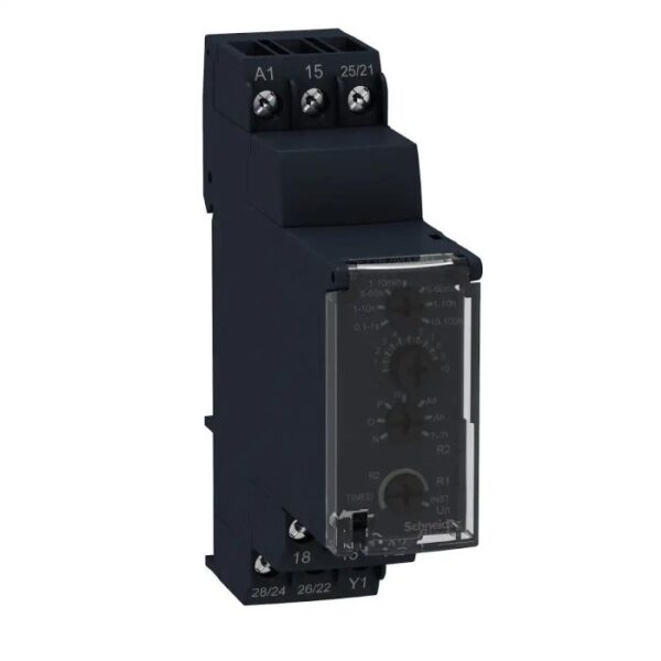
| Product or component type | Modular timing relay |
| Device short name | RE22 |
| nominal output current | 8 A |
| Complementary |
| Contacts type and composition | 1 C/O timed contact
1 C/O timed or instantaneous contact |
| Time delay type | Power on-delay
On-delay and off-delay
Interval
Off-delay
Symmetrical flashing |
| Time delay range | 0.1…1 s
6…60 s
1…10 h
1…10 min
1…10 s
10…100 h
6…60 min |
| Control type | Rotary knob front panel |
| [Us] rated supply voltage | 12…240 V AC/DC |
| Voltage range | 0.85…1.1 Us |
| Supply frequency | 50…60 Hz +/- 5 % |
| Connections – terminals | Screw terminals, 2 x 1.5 mm² with cable end
Screw terminals, 2 x 2.5 mm² without cable end |
| Tightening torque | 0.6…1 N.m conforming to IEC 60947-1 |
| Housing material | Polycarbonate |
| Repeat accuracy | +/- 0.5 % conforming to IEC 61812-1 |
| Temperature drift | +/- 0.05 %/°C |
| Voltage drift | +/- 0.2 %/V |
| Setting accuracy of time delay | +/- 10 % of full scale at 25 °C conforming to IEC 61812-1 |
| Time delay type | Power on-delay – A- Power on-delay relay
On-delay and off-delay – Ac- On-delay and off-delay relay w/ control signal
Power on-delay – At- Power on-delay relay w/ pause/summation (Y1)
Interval – B- Single interval relay w/ control signal
Interval – Bw- Double interval relay w/ control signal
Off-delay – C- Off-delay relay w/ control signal
Symmetrical flashing – D- Symmetrical flashing relay (starting pulse-off)
Symmetrical flashing – Di- Symmetrical flashing relay (starting pulse-on)
Interval – H- Interval relay
Interval – Ht- Interval relay w/ pause/summation (Y1) |
| Control signal pulse width | 30 ms
100 ms under load |
| Insulation resistance | 100 MOhm at 500 V DC conforming to IEC 60664-1 |
| Recovery time | 120 ms on de-energisation |
| Immunity to microbreaks | 10 ms |
| Power consumption in VA | 3 VA at 240 V AC |
| Power consumption in W | 1.5 W at 240 V DC |
| breaking capacity | 2000 VA |
| Minimum switching current | 10 mA at 5 V |
| Maximum switching current | 8 A |
| Maximum switching voltage | 250 V |
| Electrical durability | 100000 cycles for resistive load, 8 A at 250 V, AC |
| Mechanical durability | 10000000 cycles |
| Rated impulse withstand voltage | 5 kV for 1.2…50 µs conforming to IEC 60664-1
5 kV conforming to IEC 61812-1 |
| Power on delay | 100 ms |
| Safety reliability data | B10d = 230000
MTTFd = 251.1 years |
| Mounting position | Any position in relation to normal vertical mounting plane |
| Mounting support | 35 mm DIN rail conforming to IEC 60715 |
| Status LED | LED green (flashing) for timing in progress
LED green (steady) for power ON
LED yellow for relay energised |
| Function available | A- Power on-delay relay-2 C/O
Ac- On-delay and off-delay relay w/ control signal-2 C/O
At- Power on-delay relay w/ pause/summation (Y1)-2 C/O
B- Single interval relay w/ control signal-2 C/O
Bw- Double interval relay w/ control signal-2 C/O
C- Off-delay relay w/ control signal-2 C/O
D- Symmetrical flashing relay (starting pulse-off)-2 C/O
Di- Symmetrical flashing relay (starting pulse-on)-2 C/O
H- Interval relay-2 C/O
Ht- Interval relay w/ pause/summation (Y1)-2 C/O |
| Width | 22.5 mm |
| Product weight | 0.093 kg |
| Control type | With test button |
| Number of functions | 10 |
| Environment |
| Dielectric strength | 2.5 kV for 1 mA/1 minute at 50 Hz conforming to IEC 61812-1 |
| Standards | IEC 61812-1
IEC 61000-6-2
IEC 61000-6-1
IEC 61000-6-4
IEC 61000-6-3 |
| Directives | 2004/108/EC – electromagnetic compatibility
2006/95/EC – low voltage directive |
| Product certifications | CSA
CE
cULus
GL
RCM
CCC
EAC |
| Ambient air temperature for operation | -20…60 °C |
| Ambient air temperature for storage | -30…60 °C |
| IP degree of protection | IP40 housing: conforming to IEC 60529
IP20 terminal block: conforming to IEC 60529
IP40 front face: conforming to IEC 60529 |
| Vibration resistance | 20 m/s² (f= 10…150 Hz) conforming to IEC 60068-2-6 |
| Shock resistance | 15 gn for 11 ms conforming to IEC 60068-2-27 |
| Relative humidity | 93 %, without condensation conforming to IEC 60068-2-30 |
| Electromagnetic compatibility | Electrostatic discharge immunity test – test level: 6 kV level 3 (contact discharge) conforming to IEC 61000-4-2
Electrostatic discharge immunity test – test level: 8 kV level 3 (air discharge) conforming to IEC 61000-4-2
Fast transients immunity test – test level: 1 kV level 3 (capacitive connecting clip) conforming to IEC 61000-4-4
Fast transients immunity test – test level: 2 kV level 3 (direct contact) conforming to IEC 61000-4-4
Surge immunity test – test level: 1 kV level 3 (differential mode) conforming to IEC 61000-4-5
Surge immunity test – test level: 2 kV level 3 (common mode) conforming to IEC 61000-4-5
Radiated radio-frequency electromagnetic field immunity test – test level: 10 V level 3 (0.15…80 MHz) conforming to IEC 61000-4-6
Electromagnetic field immunity test – test level: 10 V/m level 3 (80 MHz…1 GHz) conforming to IEC 61000-4-3
Immunity to microbreaks and voltage drops – test level: 30 % (500 ms) conforming to IEC 61000-4-11
Immunity to microbreaks and voltage drops – test level: 100 % (20 ms) conforming to IEC 61000-4-11
Conducted and radiated emissions class B conforming to EN 55022 |
| Packing Units |
| Unit Type of Package 1 | PCE |
| Number of Units in Package 1 | 1 |
| Package 1 Height | 3.000 cm |
| Package 1 Width | 8.600 cm |
| Package 1 Length | 9.900 cm |
| Package 1 Weight | 108.000 g |
| Unit Type of Package 2 | S02 |
| Number of Units in Package 2 | 40 |
| Package 2 Height | 15.000 cm |
| Package 2 Width | 30.000 cm |
| Package 2 Length | 40.000 cm |
| Package 2 Weight | 4.800 kg |
| Contractual warranty |
| Warranty (in months) | 18 |