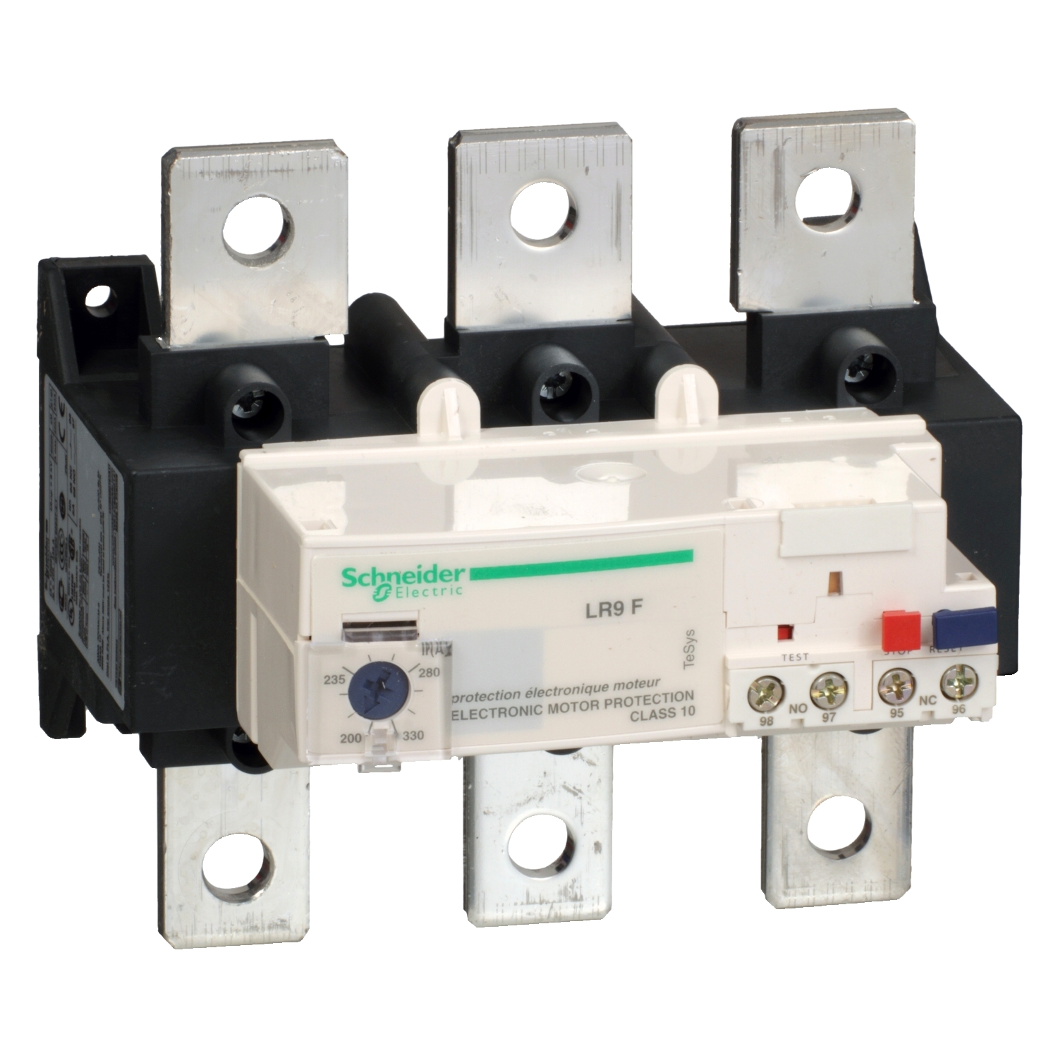
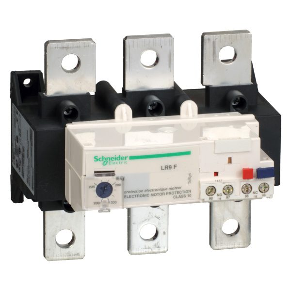
LR9F7375 | TeSys LRF – electronic thermal overload relay – 200…330 A – class 10 – Schneider Electric
₹52,725.00 Excl. GST
Out of stock
Out of stock
Order protection
Buy with complete confidence.
We back each order with genuine supply, on-time dispatch and GST or commercial invoicing as required.
The Schneider Electric LR9F7375 is an overload relay from the TeSys range, engineered for motor control and switching in demanding Indian and international installations. Key ratings include 200–330 A, 1000 V AC 50/60 Hz for power circuit, IP20. Buy the LR9F7375 | TeSys LRF – electronic thermal overload relay – 200…330 A – class 10 online at myelectric.in with GST invoice, genuine-product assurance, and fast delivery across India — bulk and worldwide export enquiries welcome.
📋 Technical Specifications
| Product | |
| Brand | Schneider Electric |
| Part Number / SKU | LR9F7375 |
| Category | Overload Relay |
| Main | |
| Range | TeSys |
| Product name | TeSys LRF |
| Device short name | LR9F |
| Product or component type | Electronic thermal overload relay |
| Relay application | Motor protection |
| Product compatibility | LC1F225…LC1F500 |
| Network type | AC |
| Thermal overload class | Class 10 conforming to IEC 60947-4 |
| Thermal protection adjustment range | 200…330 A |
| Complementary | |
| Network frequency | 50/60 Hz |
| Mounting support | Direct on contactor Plate |
| Tripping threshold | 1.12 +/- 0.06 In tripping conforming to IEC 60947-4-1 |
| Surge withstand | 4 kV conforming to IEC 61000-4-5 |
| Contacts type and composition | 1 NO + 1 NC |
| [Ith] conventional free air thermal current | 5 A for control circuit |
| [Ue] rated operational voltage | 1000 V AC 50/60 Hz for power circuit conforming to VDE 0110 group C |
| [Ui] rated insulation voltage | Power circuit: 1000 V AC conforming to IEC 60947-4 |
| [Uimp] rated impulse withstand voltage | 8 kV conforming to IEC 60947-1 |
| Phase failure sensitivity | Tripping in 4 s +/- 20 % conforming to IEC 60947-4-1 |
| Reset | Manual reset on front relay |
| Control type | Dial white full-load current adjustment Test button red Push-button red reset Push-button stop |
| Local signalling | Trip indicator |
| Temperature compensation | -20…70 °C |
| Current consumption | <= 5 mA no-load |
| switching capacity for alarm | 0…150 mA |
| Maximum voltage drop | <2.5 V closed state |
| Connections – terminals | Control circuit: screw clamp terminals 1 cable 0.75…2.5 mm² – cable stiffness: flexible – with cable end Control circuit: screw clamp terminals 1 cable 0.75…2.5 mm² – cable stiffness: solid Control circuit: screw clamp terminals 1 cable 0.75…4 mm² – cable stiffness: flexible – without cable end Control circuit: screw clamp terminals 2 cable 1…1.5 mm² – cable stiffness: flexible – with cable end Control circuit: screw clamp terminals 2 cable 1…2.5 mm² – cable stiffness: flexible – without cable end Control circuit: screw clamp terminals 2 cable 1 mm² – cable stiffness: solid Power circuit: lugs-ring terminals M10 |
| Tightening torque | Control circuit: 1.2 N.m on screw clamp terminals Power circuit: 35 N.m on screw clamp terminals |
| Height | 136.8 mm |
| Width | 150 mm |
| Depth | 127.6 mm |
| Product weight | 2.32 kg |
| Environment | |
| Standards | VDE 0660 IEC 60947-4-1 EN 60947-4-1 IEC 60255-17 IEC 60255-8 |
| Product certifications | UL CSA UKCA |
| Protective treatment | TH |
| IP degree of protection | IP20 conforming to IEC 60529 IP20 conforming to VDE 0106 |
| Ambient air temperature for operation | -20…55 °C conforming to IEC 60255-8 |
| Ambient air temperature for storage | -40…85 °C |
| Operating altitude | <= 2000 m without derating |
| Fire resistance | 850 °C conforming to IEC 60695-2-1 |
| Mechanical robustness | Shocks: 13 Gn for 11 ms conforming to IEC 60068-2-7 Vibrations 5…300 Hz: 2 GN conforming to IEC 60068-2-6 |
| Dielectric strength | 6 kV 50 Hz conforming to IEC 255-5 |
| Electromagnetic compatibility | Resistance to electrostatic discharge: 6 kV in indirect mode conforming to IEC 61000-4-2 Resistance to electrostatic discharge: 8 kV in air conforming to IEC 61000-4-2 Radiated radio-frequency electromagnetic field immunity test: 10 V/m conforming to IEC 61000-4-3 Fast transients immunity test: 2 kV conforming to IEC 61000-4-4 |
| Packing Units | |
| Unit Type of Package 1 | PCE |
| Number of Units in Package 1 | 1 |
| Package 1 Height | 18.000 cm |
| Package 1 Width | 20.000 cm |
| Package 1 Length | 19.500 cm |
| Package 1 Weight | 1.882 kg |
| Unit Type of Package 2 | P06 |
| Number of Units in Package 2 | 36 |
| Package 2 Height | 75.000 cm |
| Package 2 Width | 60.000 cm |
| Package 2 Length | 80.000 cm |
| Package 2 Weight | 79.896 kg |
| Contractual warranty | |
| Warranty (in months) | 18 |
⚡ Key Features
- Adjustable current range 200–330 A — set to the motor nameplate FLC for accurate overload detection; range covers multiple motor sizes from a single relay model.
- Class 10A trip class — trips within 10 seconds at 7.2× FLC; standard for normal-start motors (fans, pumps, compressors) where starting time is under 10 seconds.
- Bimetal thermal element with phase-loss sensitivity — independently monitors each phase; trips if any phase carries more than ~115% of the set current, or on complete phase failure.
- Normally open (NO) and normally closed (NC) auxiliary contacts built in — NO contact wired to motor run indicator; NC contact wired to PLC fault input or motor starter stop circuit.
- Direct clip-on mounting to TeSys LC1 contactors — no external wiring between overload and contactor; forms a complete IEC 60947-4-1 DOL motor starter combination.
- Manual/automatic reset selectable — set to manual for attended machinery requiring operator acknowledgement; auto-reset for unattended remote installations.
- Manufactured to IEC 60947-4-1 / IS 13947-4-1 — complies with the applicable Indian BIS and IEC international standards for this product category.
- BIS certified, CE marked, RoHS compliant — meets Indian regulatory requirements for use in government, commercial, and industrial electrical installations.
- Genuine authorised Schneider Electric product — sourced directly from the official distribution network with full manufacturer traceability and warranty.
- GST invoice provided for India orders — valid for corporate procurement, government project orders, and public tender supply via myelectric.in.
❓ Frequently Asked Questions
Q: How do I set the 200–330 A adjustable range on the LR9F7375 for my motor?
A: Turn the setting dial to the motor’s nameplate full-load current (FLC) — the FLC must fall within the 200–330 A range of this device. Setting it at the motor FLC (not the maximum of the range) gives correct overload trip timing while still riding through normal starting inrush. If the motor FLC is outside this range, select the adjacent rating in the same series.
Q: How do I set the LR9F7375 to protect a motor without causing nuisance trips on starting?
A: Set the thermal overload dial to the motor’s nameplate full-load current (FLC) — ensure the FLC is within the 200–330 A range of this relay. For star-delta starters, set the overload relay to 58% of motor FLC (line current in delta = FLC × 0.58). Allow 10 trips for the relay’s thermal memory to stabilise before adjusting the setting.
Q: Does the LR9F7375 provide single-phase (phase loss) protection?
A: Schneider Electric thermal overload relays include single-phase sensitivity: if one phase is lost, the remaining phases carry higher current, causing the bimetal to heat and trip within the specified time. For critical motors, add a dedicated phase-loss relay for faster response independent of load — overload relay phase-loss protection is load-dependent and may take minutes to trip at light load.
Q: What is the difference between an Overload Relay and a standard MCB — and why use the LR9F7375?
A: A standard MCB protects against overload and short-circuit only. An Overload Relay provides thermal overload protection calibrated to motor FLC, protecting the motor from sustained overloads that would destroy windings before a standard MCB trips. Choose the LR9F7375 when the application specifically requires overload relay characteristics.