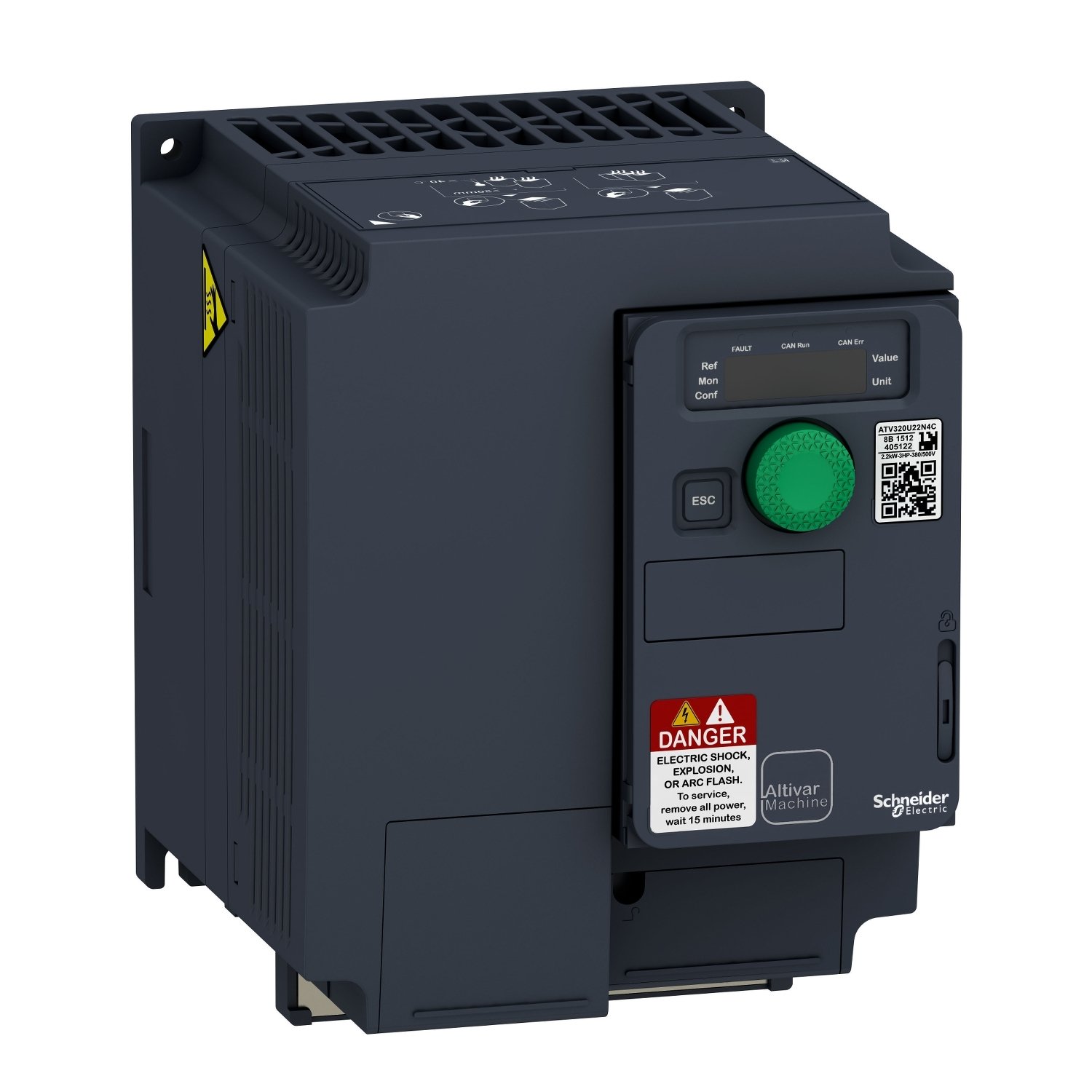
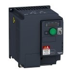
ATV320U30N4C | variable speed drive, Altivar Machine ATV320, 3kW, 380 to 500V, 3 phases, compact – Schneider Electric
₹63,844.00 Original price was: ₹63,844.00.₹22,983.84Current price is: ₹22,983.84. Excl. GST
Dispatch By : 2 Weeks
Order protection
Buy with complete confidence.
We back each order with genuine supply, on-time dispatch and GST or commercial invoicing as required.
Additional Addons/Accessories
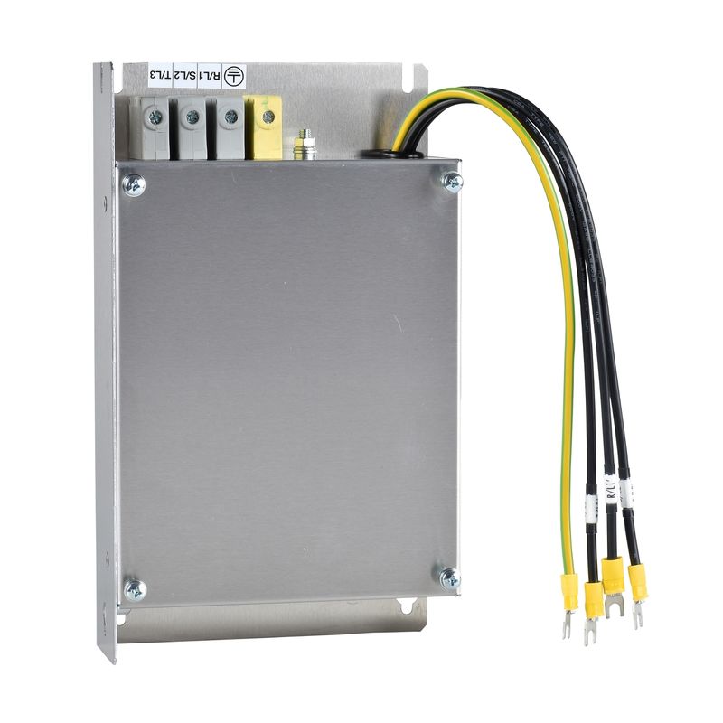
VW3A31406 | EMC FILTER S7 M3-S7 N4 – Schneider Electric
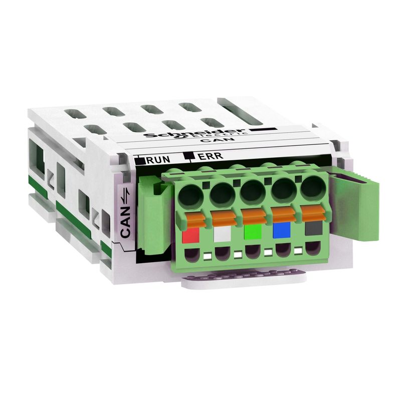
VW3A3628 | ELECTRONIC OPTION CARD CANOPEN CONNECTOR – Schneider Electric
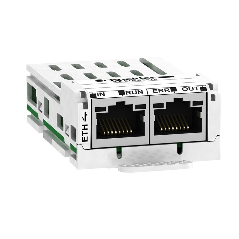
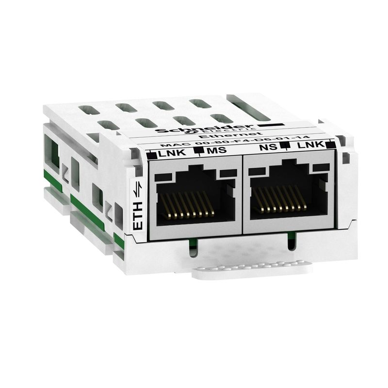
VW3A3616 | ELECTRONIC OPTION CARD ETHERNET TCP-IP A – Schneider Electric
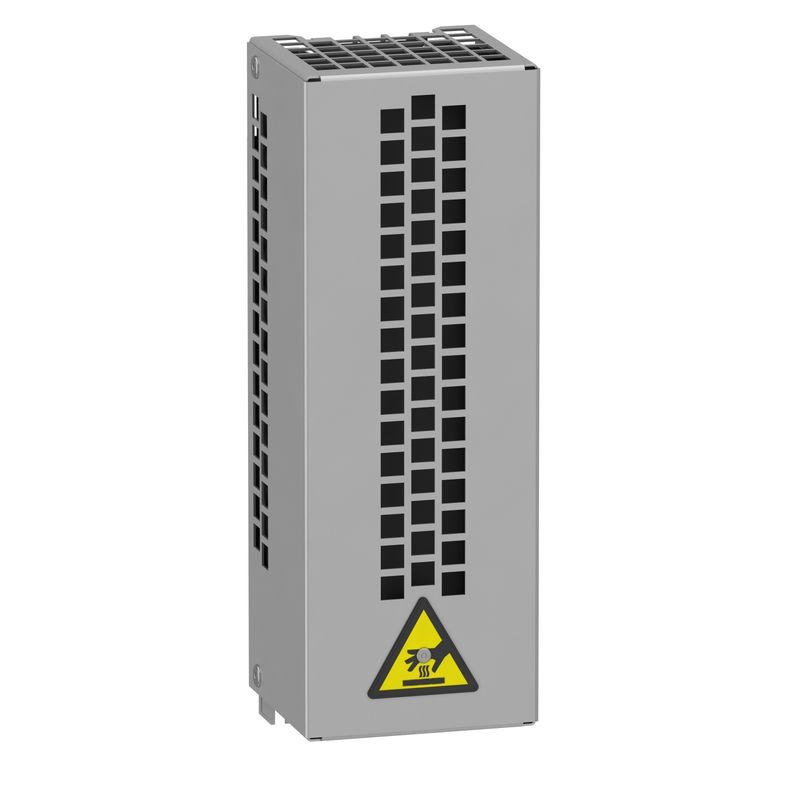
VW3A7730 | BRAKING RESISTOR 100 OHMS 0,1 KW IP20 – Schneider Electric
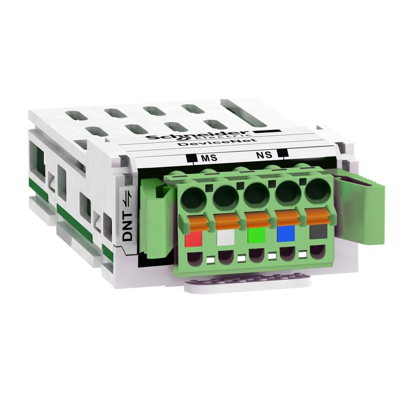
VW3A3609 | ELECTRONIC CARD DEVICENET ATV32 – Schneider Electric
VW3A3600 | Communication adapter card for ATV320C – Schneider Electric
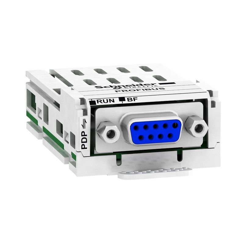
VW3A3607 | ELECTRONIC OPTION CARD PROFIBUS – Schneider Electric
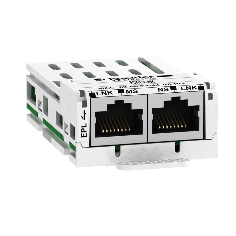
VW3A3619 | ATV320 POWERLINK FIELDBUS MODULE – Schneider Electric
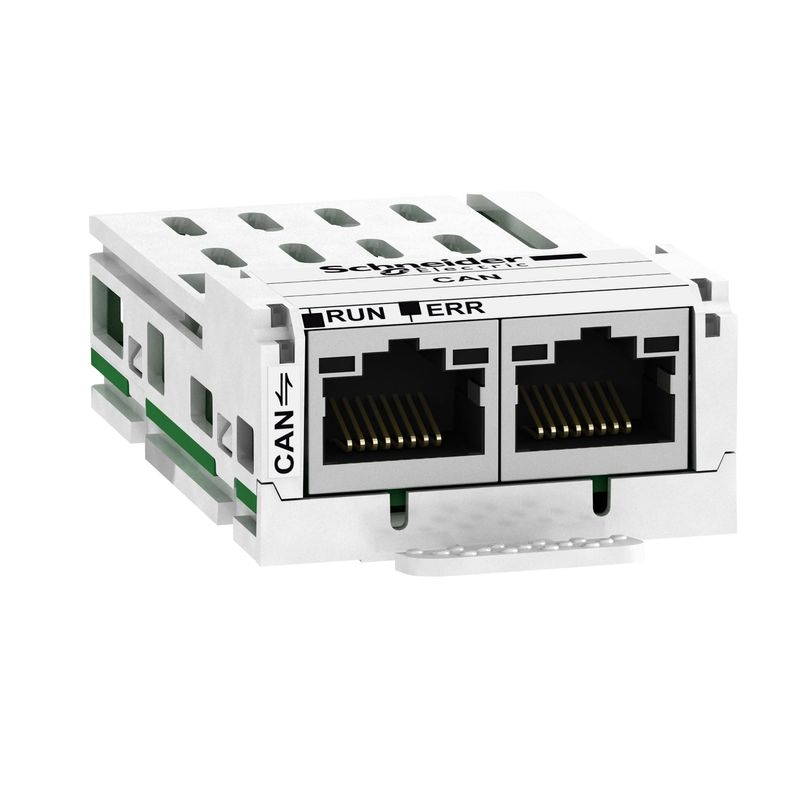
VW3A3608 | ELECTRONIC OPTION CARD CANOPEN 2XRJ45 AT – Schneider Electric
VW3A3601 | ETHERCAT DAISY CHAIN COMMUNICATION CARD – Schneider Electric
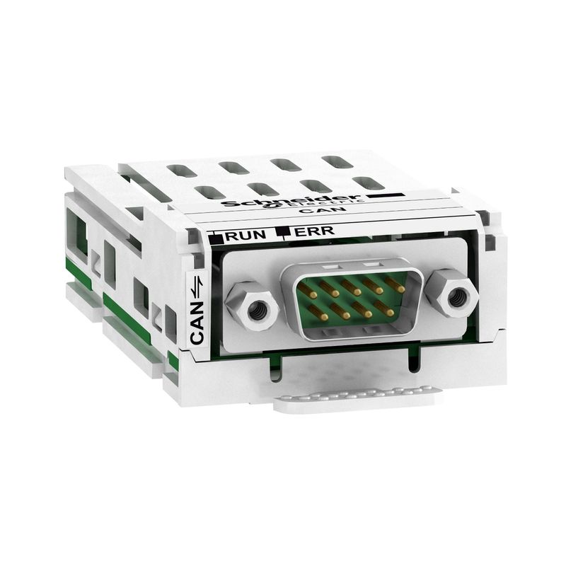
VW3A3618 | ELECTRONIC OPTION CARD CANOPEN SUBD9 ATV – Schneider Electric
Sourced through authorised channels, the Schneider Electric ATV320U30N4C variable frequency drive (vfd) from the Altivar Machine ATV320 range delivers dependable performance for variable-speed motor control and energy savings. Key ratings include 380–500V AC, IP20. myelectric.in stocks the ATV320U30N4C | variable speed drive, Altivar Machine ATV320, 3kW, 380 to 500V, 3 phases, compact for contractors, panel builders, and project buyers — buy online with GST invoice, or request a bulk quote for domestic supply and export to UAE, Singapore, UK, USA, Sri Lanka and more.
📋 Technical Specifications
| Product | |
| Brand | Schneider Electric |
| Part Number / SKU | ATV320U30N4C |
| Category | Variable Frequency Drive (VFD) |
| Main | |
| Range of product | Altivar Machine ATV320 |
| Product or component type | Variable speed drive |
| Product specific application | Complex machines |
| Variant | Standard version |
| Format of the drive | Compact |
| Mounting mode | Wall mount |
| Communication port protocol | Modbus serial CANopen |
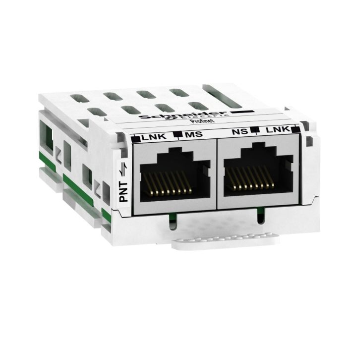
| Option card | Communication module, CANopen Communication module, EtherCAT Communication module, Profibus DP V1 Communication module, PROFINET Communication module, Ethernet Powerlink Communication module, EtherNet/IP Communication module, DeviceNet |
| [Us] rated supply voltage | 380…500 V – 15…10 % |
| nominal output current | 7.1 A |
| Motor power kW | 3.0 kW for heavy duty |
| EMC filter | Class C2 EMC filter integrated |
| IP degree of protection | IP20 |
| Complementary | |
| Discrete input number | 7 |
| Discrete input type | STO safe torque off, 24 V DC, impedance: 1.5 kOhm DI1…DI6 logic inputs, 24 V DC (30 V) DI5 programmable as pulse input: 0…30 kHz, 24 V DC (30 V) |
| Discrete input logic | Positive logic (source) Negative logic (sink) |
| Discrete output number | 3 |
| Discrete output type | Open collector DQ+ 0…1 kHz 30 V DC 100 mA Open collector DQ- 0…1 kHz 30 V DC 100 mA |
| Analogue input number | 3 |
| Analogue input type | AI1 voltage: 0…10 V DC, impedance: 30 kOhm, resolution 10 bits AI2 bipolar differential voltage: +/- 10 V DC, impedance: 30 kOhm, resolution 10 bits AI3 current: 0…20 mA (or 4-20 mA, x-20 mA, 20-x mA or other patterns by configuration), impedance: 250 Ohm, resolution 10 bits |
| Analogue output number | 1 |
| Analogue output type | Software-configurable current AQ1: 0…20 mA impedance 800 Ohm, resolution 10 bits Software-configurable voltage AQ1: 0…10 V DC impedance 470 Ohm, resolution 10 bits |
| Relay output type | Configurable relay logic R1A 1 NO electrical durability 100000 cycles Configurable relay logic R1B 1 NC electrical durability 100000 cycles Configurable relay logic R1C Configurable relay logic R2A 1 NO electrical durability 100000 cycles Configurable relay logic R2C |
| Maximum switching current | Relay output R1A, R1B, R1C on resistive load, cos phi = 1: 3 A at 250 V AC Relay output R1A, R1B, R1C on resistive load, cos phi = 1: 3 A at 30 V DC Relay output R1A, R1B, R1C, R2A, R2C on inductive load, cos phi = 0.4 and L/R = 7 ms: 2 A at 250 V AC Relay output R1A, R1B, R1C, R2A, R2C on inductive load, cos phi = 0.4 and L/R = 7 ms: 2 A at 30 V DC Relay output R2A, R2C on resistive load, cos phi = 1: 5 A at 250 V AC Relay output R2A, R2C on resistive load, cos phi = 1: 5 A at 30 V DC |
| Minimum switching current | Relay output R1A, R1B, R1C, R2A, R2C: 5 mA at 24 V DC |
| Method of access | Slave CANopen |
| 4 quadrant operation possible | True |
| Asynchronous motor control profile | Voltage/frequency ratio, 5 points Flux vector control without sensor, standard Voltage/frequency ratio – Energy Saving, quadratic U/f Flux vector control without sensor – Energy Saving Voltage/frequency ratio, 2 points |
| Synchronous motor control profile | Vector control without sensor |
| Maximum output frequency | 0.599 kHz |
| Acceleration and deceleration ramps | Linear U S CUS Ramp switching Acceleration/deceleration ramp adaptation Acceleration/deceleration automatic stop with DC injection |
| Motor slip compensation | Automatic whatever the load Adjustable 0…300 % Not available in voltage/frequency ratio (2 or 5 points) |
| Switching frequency | 2…16 kHz adjustable 4…16 kHz with derating factor |
| Nominal switching frequency | 4 kHz |
| Braking to standstill | By DC injection |
| Brake chopper integrated | True |
| Line current | 11.1 A at 380 V (heavy duty) 8.4 A at 500 V (heavy duty) |
| Maximum input current | 11.1 A |
| Maximum output voltage | 500 V |
| Apparent power | 7.3 kVA at 500 V (heavy duty) |
| Network frequency | 50…60 Hz |
| Relative symmetric network frequency tolerance | 5 % |
| Prospective line Isc | 5 kA |
| Base load current at high overload | 7.1 A |
| Power dissipation in W | Fan: 93.0 W at 380 V, switching frequency 4 kHz |
| With safety function Safely Limited Speed (SLS) | True |
| With safety function Safe brake management (SBC/SBT) | False |
| With safety function Safe Operating Stop (SOS) | False |
| With safety function Safe Position (SP) | False |
| With safety function Safe programmable logic | False |
| With safety function Safe Speed Monitor (SSM) | False |
| With safety function Safe Stop 1 (SS1) | True |
| With sft fct Safe Stop 2 (SS2) | False |
| With safety function Safe torque off (STO) | True |
| With safety function Safely Limited Position (SLP) | False |
| With safety function Safe Direction (SDI) | False |
| Protection type | Input phase breaks: drive Overcurrent between output phases and earth: drive Overheating protection: drive Short-circuit between motor phases: drive Thermal protection: drive |
| Width | 140 mm |
| Height | 184.0 mm |
| Depth | 158.0 mm |
| Product weight | 2.1 kg |
| Transient overtorque | 170…200 % of nominal motor torque |
| Environment | |
| Operating position | Vertical +/- 10 degree |
| Product certifications | CE ATEX NOM GOST EAC RCM KC |
| Marking | CE ATEX UL CSA EAC RCM |
| Standards | IEC 61800-5-1 |
| Electromagnetic compatibility | Electrostatic discharge immunity test level 3 conforming to IEC 61000-4-2 Radiated radio-frequency electromagnetic field immunity test level 3 conforming to IEC 61000-4-3 Electrical fast transient/burst immunity test level 4 conforming to IEC 61000-4-4 1.2/50 µs – 8/20 µs surge immunity test level 3 conforming to IEC 61000-4-5 Conducted radio-frequency immunity test level 3 conforming to IEC 61000-4-6 Voltage dips and interruptions immunity test conforming to IEC 61000-4-11 |
| Environmental class (during operation) | Class 3C3 according to IEC 60721-3-3 Class 3S2 according to IEC 60721-3-3 |
| Maximum acceleration under shock impact (during operation) | 150 m/s² at 11 ms |
| Maximum acceleration under vibrational stress (during operation) | 10 m/s² at 13…200 Hz |
| Maximum deflection under vibratory load (during operation) | 1.5 mm at 2…13 Hz |
| Permitted relative humidity (during operation) | Class 3K5 according to EN 60721-3 |
| Volume of cooling air | 37.7 m3/h |
| Overvoltage category | III |
| Regulation loop | Adjustable PID regulator |
| Speed accuracy | +/- 10 % of nominal slip 0.2 Tn to Tn |
| Pollution degree | 2 |
| Ambient air transport temperature | -25…70 °C |
| Ambient air temperature for operation | -10…50 °C without derating 50…60 °C with derating factor |
| Ambient air temperature for storage | -25…70 °C |
| Packing Units | |
| Unit Type of Package 1 | PCE |
| Number of Units in Package 1 | 1 |
| Package 1 Height | 19.300 cm |
| Package 1 Width | 27.000 cm |
| Package 1 Length | 24.500 cm |
| Package 1 Weight | 2.690 kg |
| Unit Type of Package 2 | S06 |
| Number of Units in Package 2 | 12 |
| Package 2 Height | 75.000 cm |
| Package 2 Width | 60.000 cm |
| Package 2 Length | 80.000 cm |
| Package 2 Weight | 45.640 kg |
| Contractual warranty | |
| Warranty (in months) | 18 |
⚡ Key Features
- Rated for a 3 kW three-phase motor — adjustable output frequency from near 0 to 50/60 Hz gives stepless speed control for pumps, fans, compressors, and conveyor drives.
- Soft-start acceleration ramp — limits motor starting current to ~1.5× FLC vs. the 6–7× FLC of DOL starting; eliminates mechanical shock on gearboxes, belts, and couplings and reduces peak demand charges.
- Built-in electronic motor protection — overload, phase-loss, overvoltage (+10%), undervoltage, and short-circuit protection without additional external relays.
- Altivar series VFD — compatible with Schneider SoMove PC commissioning software; parameter upload/download for rapid commissioning of multiple drives.
- Manufactured to IEC 61800-5-1 (safety) and IEC 61800-3 (EMC) — complies with the applicable Indian BIS and IEC international standards for this product category.
- BIS certified, CE marked, RoHS compliant — meets Indian regulatory requirements for use in government, commercial, and industrial electrical installations.
- Genuine authorised Schneider Electric product — sourced directly from the official distribution network with full manufacturer traceability and warranty.
- GST invoice provided for India orders — valid for corporate procurement, government project orders, and public tender supply via myelectric.in.
- Worldwide export available — UAE, Singapore, UK, USA, Sri Lanka & more. Contact +91 94814 00316 for bulk pricing and international shipping.
🔗 Compatible Products & Accessories
The following genuine accessories and compatible devices are designed to work with this product. Contact myelectric.in for pricing and availability:
❓ Frequently Asked Questions
Q: Can the ATV320U30N4C be used to control a 3 kW motor with soft start and variable speed?
A: Yes. This VFD is rated for a 3 kW motor load and provides stepless speed control from 0 to rated frequency (typically 0–50 Hz). The soft-start ramp eliminates mechanical shock and reduces starting current from typically 6–7× FLC to just 1–1.5× FLC. Ensure the motor cable length does not exceed the VFD manufacturer’s maximum (typically 50–100m without output filter) to avoid insulation stress.
Q: Can the ATV320U30N4C run a standard squirrel-cage induction motor without modification?
A: Yes — standard squirrel-cage induction motors rated for 415V 50Hz can be driven by this VFD. However, at low speeds (<20 Hz), motor cooling is reduced because the shaft-mounted fan slows down. For extended low-speed operation, fit a separately powered external cooling fan on the motor, or use a motor specified for inverter duty.
Q: Does the ATV320U30N4C require an input line reactor or output filter for protection?
A: For installations with poor power quality (voltage spikes, harmonics), an input line reactor (3–5% impedance) extends the ATV320U30N4C’s life by reducing diode stress and lowering harmonic injection. An output dV/dt filter is recommended when motor cable exceeds 50m to prevent reflected wave damage to motor insulation, especially on older motors not rated for VFD use.
Q: Does the ATV320U30N4C inject harmonics into the supply and is a line reactor required?
A: VFDs including the ATV320U30N4C generate harmonic currents (primarily 5th and 7th order) due to their diode rectifier front-end. In installations where total harmonic distortion (THD) is a concern — such as facilities with sensitive medical or measurement equipment, or where multiple large drives share a common bus — a 3% or 5% impedance line reactor on the input significantly reduces harmonic injection and protects the drive’s DC bus capacitors from voltage spikes. Check if your site’s power quality specification sets a THD limit.