


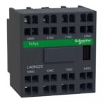
LADN223 | TeSys CONTACTS BLOCK - Schneider Electric
Original price was: ₹3,555.00.₹3,057.30Current price is: ₹3,057.30. Excl. GST
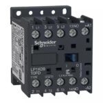
LP1K0910GD | CONTACTOR - Schneider Electric
Original price was: ₹6,190.00.₹2,785.50Current price is: ₹2,785.50. Excl. GST
-55%

Additional Addons/Accessories

-55%
LADS2 | TeSys D – time delay auxiliary contact block – 1 NO + 1 NC screw clamp terminals – Schneider Electric
Original price was: ₹7,350.00.₹3,307.50Current price is: ₹3,307.50. Excl. GST
SKU:
LADS2

-55%
LAD9V6 | DOWNSTREAM BUS BAR SCREW – Schneider Electric
Original price was: ₹1,485.00.₹668.25Current price is: ₹668.25. Excl. GST
SKU:
LAD9V6

-55%
LADT0 | TeSys D – time delay auxiliary contact block – 1 NO + 1 NC screw clamp terminals – Schneider Electric
Original price was: ₹6,895.00.₹3,102.75Current price is: ₹3,102.75. Excl. GST
SKU:
LADT0
-55%
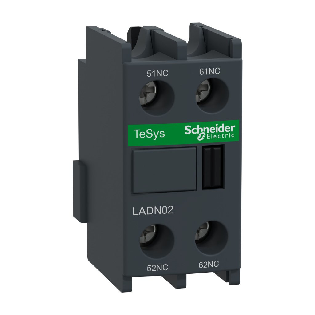
LADN02 | Auxiliary contact block, TeSys D, 2NC, front mounting, screw clamp terminals – Schneider Electric
Original price was: ₹1,065.00.₹479.25Current price is: ₹479.25. Excl. GST
SKU:
LADN02
-55%
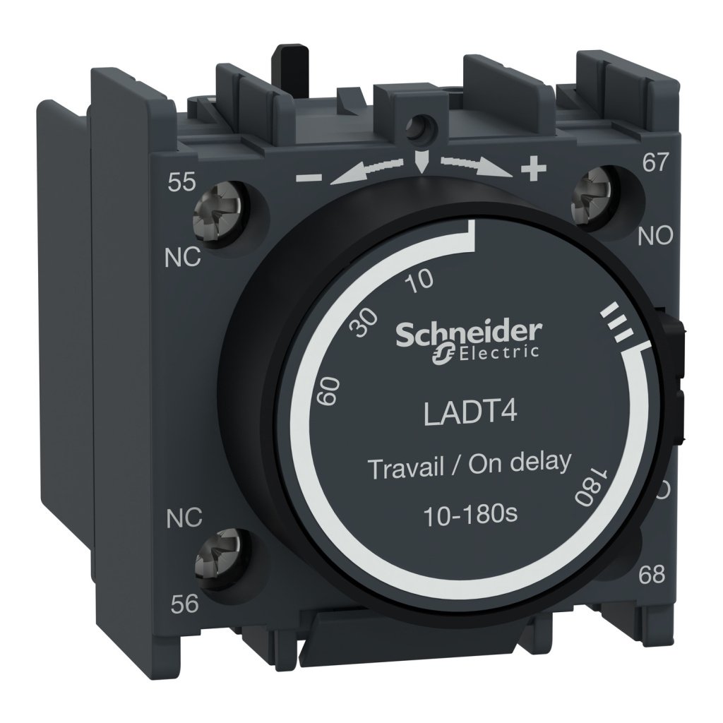
LADT4 | TeSys D – time delay auxiliary contact block – 1 NO + 1 NC screw clamp terminals – Schneider Electric
Original price was: ₹6,895.00.₹3,102.75Current price is: ₹3,102.75. Excl. GST
SKU:
LADT4
-15%
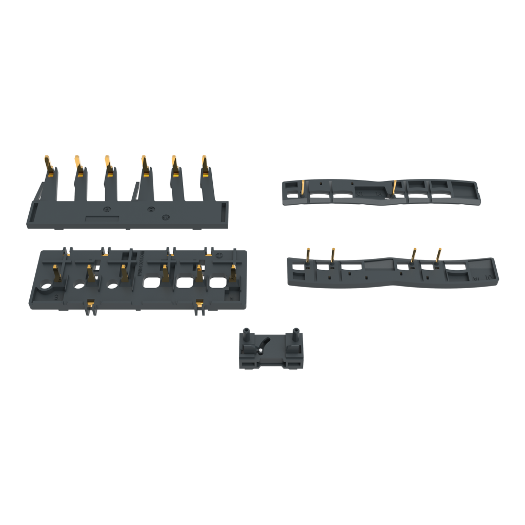
LAD9R1V | Kit for assembling 3P reversing contactors, LC1D09-D38 with screw clamp terminals, with electrical interlock – Schneider Electric
Original price was: ₹2,970.00.₹2,524.50Current price is: ₹2,524.50. Excl. GST
SKU:
LAD9R1V
-55%
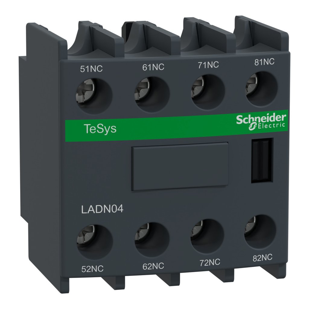
LADN04 | Auxiliary contact block, TeSys D, 4NC, front mounting, screw clamp terminals – Schneider Electric
Original price was: ₹2,555.00.₹1,149.75Current price is: ₹1,149.75. Excl. GST
SKU:
LADN04

-55%
LADN13 | Auxiliary contact block, TeSys D, 1NO + 3NC, front mounting, screw clamp terminals – Schneider Electric
Original price was: ₹1,740.00.₹783.00Current price is: ₹783.00. Excl. GST
SKU:
LADN13

-55%
LADN22 | Auxiliary contact block, TeSys D, 2NO + 2NC, front mounting, screw clamp terminals – Schneider Electric
Original price was: ₹1,740.00.₹783.00Current price is: ₹783.00. Excl. GST
SKU:
LADN22

-15%
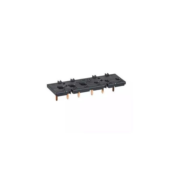
LAD9R1 | Kit for assembling 3P reversing contactors, LC1D09-D38 with screw clamp terminals, without electrical interlock – Schneider Electric
Original price was: ₹2,995.00.₹2,545.75Current price is: ₹2,545.75. Excl. GST
SKU:
LAD9R1

-55%
LADT2 | TeSys D – time delay auxiliary contact block – 1 NO + 1 NC screw clamp terminals – Schneider Electric
Original price was: ₹6,895.00.₹3,102.75Current price is: ₹3,102.75. Excl. GST
SKU:
LADT2

-55%
LADN11 | Auxiliary contact block, TeSys D, 1NO + 1NC, front mounting, screw clamp terminals – Schneider Electric
Original price was: ₹955.00.₹429.75Current price is: ₹429.75. Excl. GST
SKU:
LADN11

-15%
LAD9V2 | Mechanical interlock, TeSys D contactors LC1D09-D38 LC1DT20-DT40 – Schneider Electric
Original price was: ₹1,430.00.₹1,215.50Current price is: ₹1,215.50. Excl. GST
SKU:
LAD9V2

-55%
LADN20 | Auxiliary contact block, TeSys D, 2NO, front mounting, screw clamp terminals – Schneider Electric
Original price was: ₹1,045.00.₹470.25Current price is: ₹470.25. Excl. GST
SKU:
LADN20

-55%
LAD9ET1S | TeSys SAFETY COVER RED FOR 09-38A – 40 – Schneider Electric
Original price was: ₹1,370.00.₹616.50Current price is: ₹616.50. Excl. GST
SKU:
LAD9ET1S
-55%
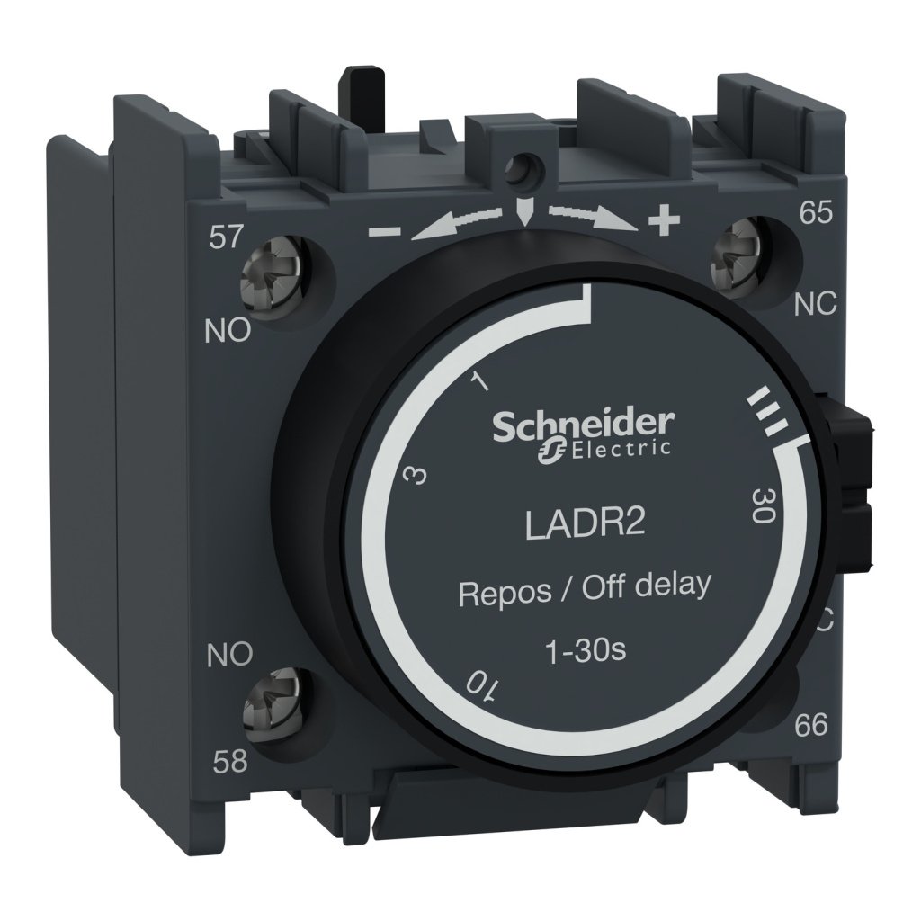
LADR2 | TeSys D – time delay auxiliary contact block – 1 NO + 1 NC screw clamp terminals – Schneider Electric
Original price was: ₹6,895.00.₹3,102.75Current price is: ₹3,102.75. Excl. GST
SKU:
LADR2
-52%
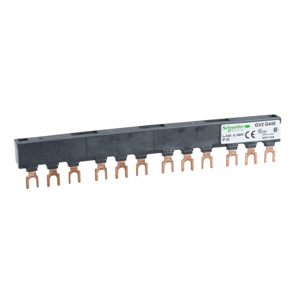
GV2G445 | Linergy FT – Comb busbar – 63 A – 4 tap-offs – 45 mm pitch – Schneider Electric
Original price was: ₹6,290.00.₹3,019.20Current price is: ₹3,019.20. Excl. GST
SKU:
GV2G445

-55%
LADN40 | Auxiliary contact block, TeSys D, 4NO, front mounting, screw clamp terminals – Schneider Electric
Original price was: ₹1,740.00.₹783.00Current price is: ₹783.00. Excl. GST
SKU:
LADN40
-55%
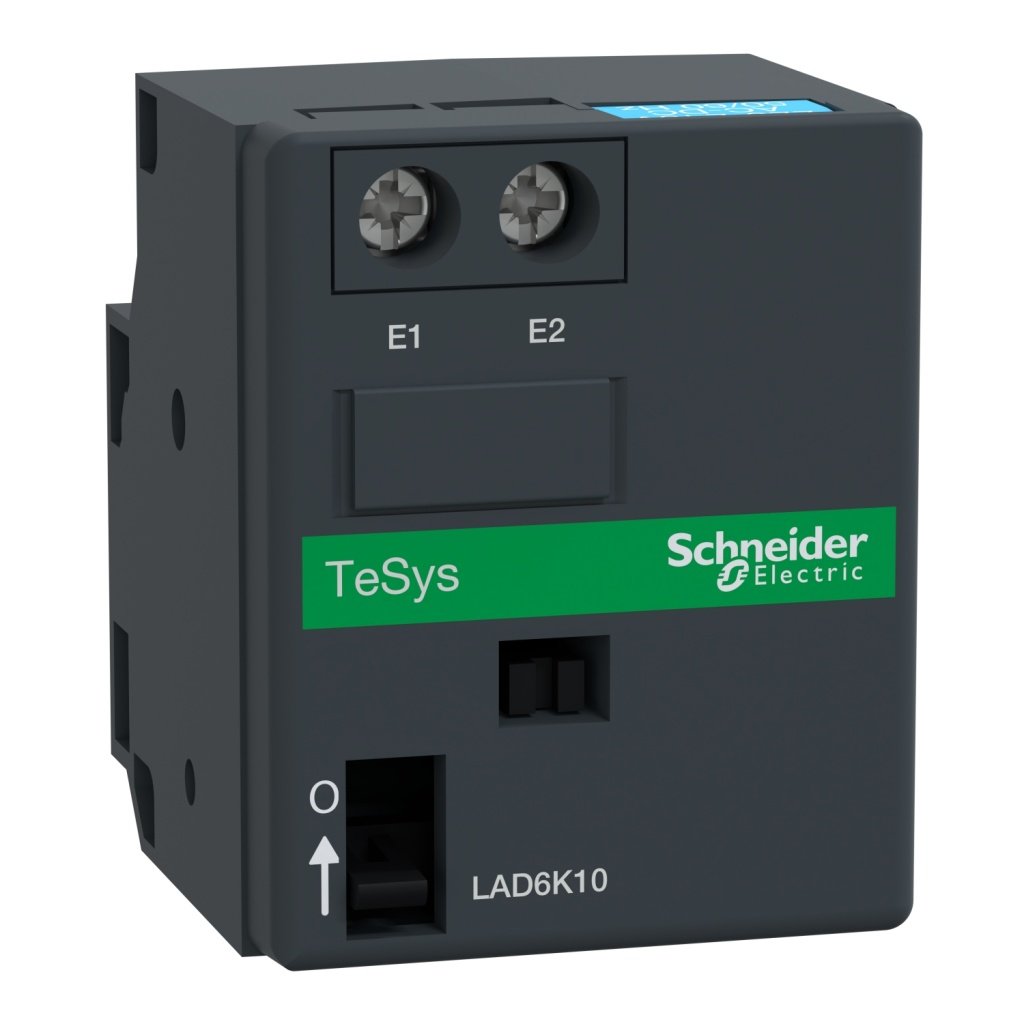
LAD6K10M | CONTACTOR MECH. LATCH CONTACT BLOCK IEC – Schneider Electric
Original price was: ₹13,065.00.₹5,879.25Current price is: ₹5,879.25. Excl. GST
SKU:
LAD6K10M
-55%
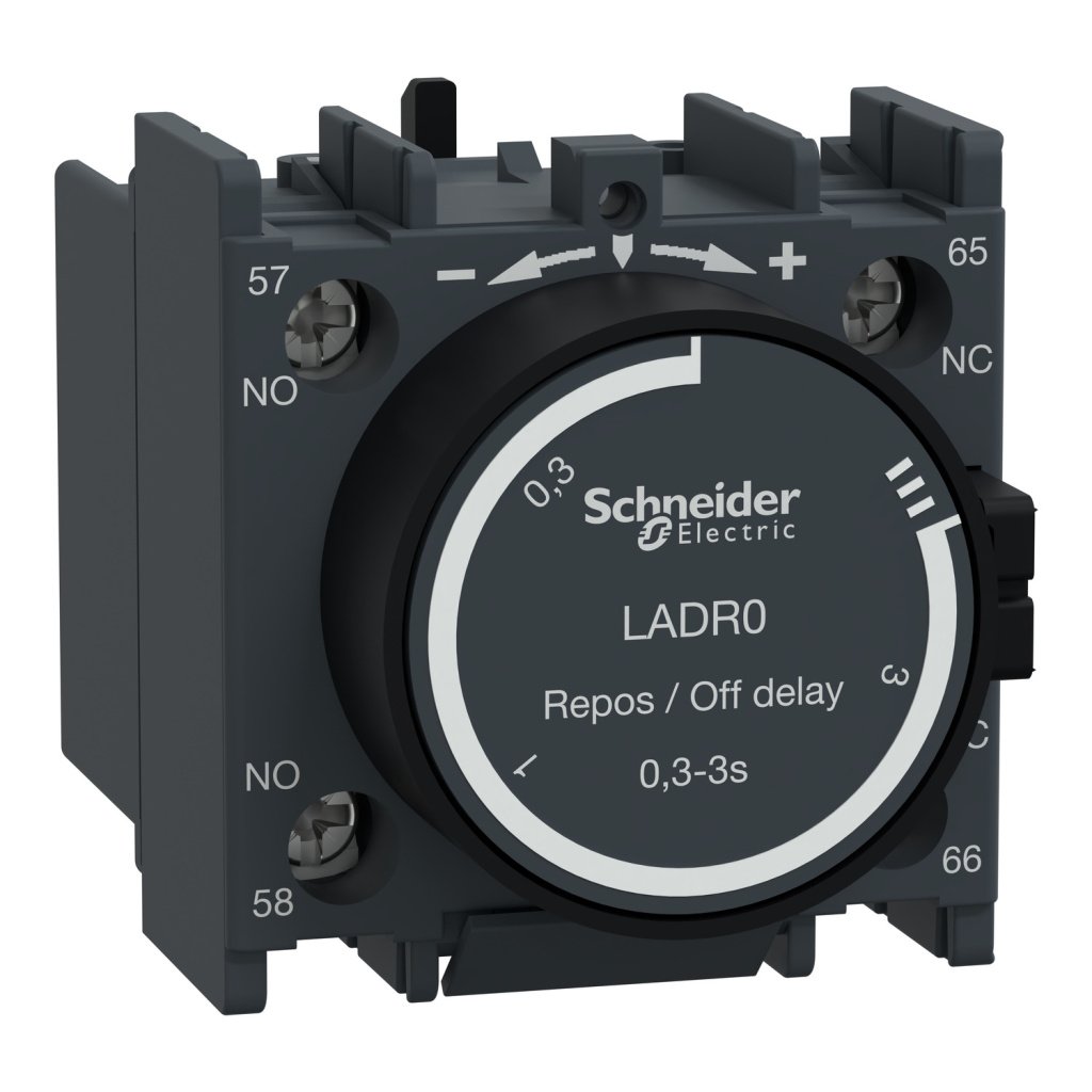
LADR0 | TeSys D – time delay auxiliary contact block – 1 NO + 1 NC screw clamp terminals – Schneider Electric
Original price was: ₹6,895.00.₹3,102.75Current price is: ₹3,102.75. Excl. GST
SKU:
LADR0

-55%
LAD4DDL | FREE WHEELING DIODE 24-250VAC D09-D38 – Schneider Electric
Original price was: ₹4,860.00.₹2,187.00Current price is: ₹2,187.00. Excl. GST
SKU:
LAD4DDL
-55%
LAD9V5 | UPSTREAM BUS BAR SCREW – Schneider Electric
Original price was: ₹1,185.00.₹533.25Current price is: ₹533.25. Excl. GST
SKU:
LAD9V5

-55%
LADN31 | Auxiliary contact block, TeSys D, 3NO + 1NC, front mounting, screw clamp terminals – Schneider Electric
Original price was: ₹1,740.00.₹783.00Current price is: ₹783.00. Excl. GST
SKU:
LADN31
-56%
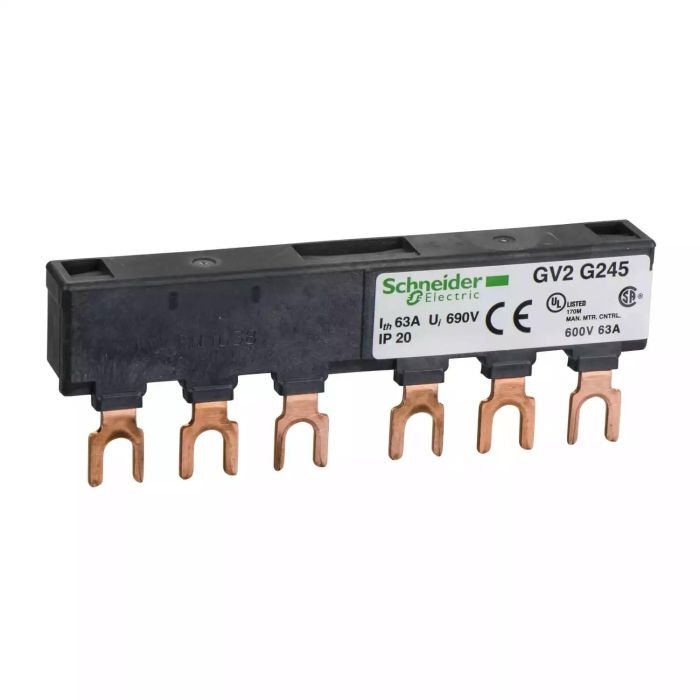
GV2G245 | 2 TAP OFFS BUSBAR GV2 63A 45MM PITCH – Schneider Electric
Original price was: ₹4,000.00.₹1,760.00Current price is: ₹1,760.00. Excl. GST
SKU:
GV2G245
-55%
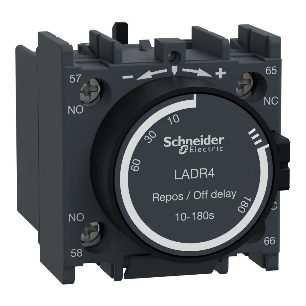
LADR4 | TeSys D – time delay auxiliary contact block – 1 NO + 1 NC screw clamp terminals – Schneider Electric
Original price was: ₹6,895.00.₹3,102.75Current price is: ₹3,102.75. Excl. GST
SKU:
LADR4
Related Products


-46%
XB5AR31N | Push button, Harmony XB5N XB7N, plastic, mushroom, green, 60mm, spring return, unmarked, 1 NO – Schneider Electric
Original price was: ₹675.00.₹364.50Current price is: ₹364.50. Excl. GST
SKU:
XB5AR31N

-35%
ZB2BW36C | Ø 22 mm fixing hole – push button head with blue lamp – Schneider Electric
Original price was: ₹305.00.₹198.25Current price is: ₹198.25. Excl. GST
SKU:
ZB2BW36C
-20%
MS13MD09 | 7MDL, 1HP 3 PHASE DOL STARTER – Schneider Electric
Original price was: ₹5,530.00.₹4,424.00Current price is: ₹4,424.00. Excl. GST
SKU:
MS13MD09
-50%
30002572 | EM1200 Energy meter Cl 0.5 RS485 LCD – Schneider Electric
Original price was: ₹6,271.00.₹3,135.50Current price is: ₹3,135.50. Excl. GST
SKU:
30002572