| Product |
| Brand | Schneider Electric |
| Part Number / SKU | LC2D25F7 |
| Category | Electrical Component |
| Main |
| Range | TeSys
TeSys Deca |
| Product name | TeSys Deca
TeSys Deca |
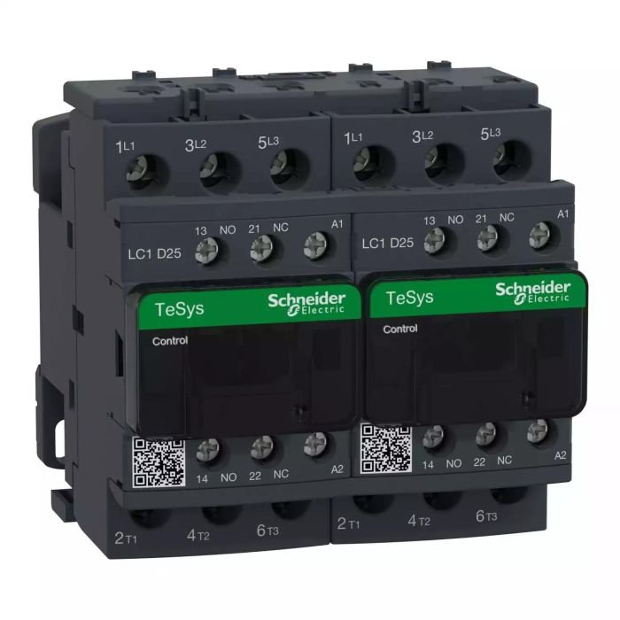
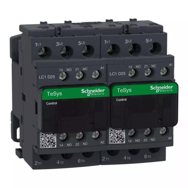
| Product or component type | Reversing contactor |
| Device short name | LC2D |
| Contactor application | Resistive load
Motor control |
| Utilisation category | AC-1
AC-3
AC-3e |
| Device presentation | Preassembled with reversing power busbar |
| Poles description | 3P |
| power pole contact composition | 3 NO |
| [Ue] rated operational voltage | Power circuit: <= 690 V AC 25…400 Hz
Power circuit: <= 300 V DC |
| [Ie] rated operational current | 25 A (at <60 °C) at <= 440 V AC AC-3 for power circuit
40 A (at <60 °C) at <= 440 V AC AC-1 for power circuit |
| Motor power kW | 5.5 kW at 220…230 V AC 50…60 Hz
11 kW at 380…400 V AC 50…60 Hz
11 kW at 415 V AC 50…60 Hz
11 kW at 440 V AC 50…60 Hz
15 kW at 500 V AC 50…60 Hz
15 kW at 660…690 V AC 50…60 Hz |
| Motor power hp | 3 hp at 230/240 V AC 60 Hz for 1 phase motors
5 hp at 200/208 V AC 60 Hz for 3 phases motors
2 hp at 115 V AC 60 Hz for 1 phase motors
7.5 hp at 230/240 V AC 60 Hz for 3 phases motors
15 hp at 460/480 V AC 60 Hz for 3 phases motors
20 hp at 575/600 V AC 60 Hz for 3 phases motors |
| Control circuit type | AC at 50/60 Hz |
| [Uc] control circuit voltage | 110 V AC 50/60 Hz |
| Auxiliary contact composition | 1 NO + 1 NC |
| [Uimp] rated impulse withstand voltage | 6 kV conforming to IEC 60947 |
| Overvoltage category | III |
| [Ith] conventional free air thermal current | 10 A (at 60 °C) for signalling circuit
40 A (at 60 °C) for power circuit |
| Irms rated making capacity | 140 A AC for signalling circuit conforming to IEC 60947-5-1
250 A DC for signalling circuit conforming to IEC 60947-5-1
450 A at 440 V for power circuit conforming to IEC 60947 |
| Rated breaking capacity | 450 A at 440 V for power circuit conforming to IEC 60947 |
| [Icw] rated short-time withstand current | 50 A 40 °C – 10 min for power circuit
120 A 40 °C – 1 min for power circuit
240 A 40 °C – 10 s for power circuit
380 A 40 °C – 1 s for power circuit
100 A – 1 s for signalling circuit
120 A – 500 ms for signalling circuit
140 A – 100 ms for signalling circuit |
| Associated fuse rating | 10 A gG for signalling circuit conforming to IEC 60947-5-1
63 A gG at <= 690 V coordination type 1 for power circuit
40 A gG at <= 690 V coordination type 2 for power circuit |
| Average impedance | 2 mOhm – Ith 40 A 50 Hz for power circuit |
| [Ui] rated insulation voltage | Power circuit: 690 V conforming to IEC 60947-4-1
Power circuit: 600 V CSA certified
Power circuit: 600 V UL certified
Signalling circuit: 690 V conforming to IEC 60947-1
Signalling circuit: 600 V CSA certified
Signalling circuit: 600 V UL certified |
| Electrical durability | 1.65 Mcycles 25 A AC-3 at Ue <= 440 V
1.4 Mcycles 40 A AC-1 at Ue <= 440 V
1.65 Mcycles 25 A AC-3e at Ue <= 440 V |
| Power dissipation per pole | 1.25 W AC-3
3.2 W AC-1
1.25 W AC-3e |
| Front cover | With |
| Interlocking type | Mechanical |
| Mounting support | Rail
Plate |
| Standards | CSA C22.2 No 14
EN 60947-4-1
EN 60947-5-1
IEC 60947-4-1
IEC 60947-5-1
UL 60335-2-40:Annex JJ
IEC 60335-1 |
| Product certifications | DNV
CSA
CCC
UL
GL
LROS (Lloyds register of shipping)
BV
RINA
GOST
UKCA
CB |
| Connections – terminals | Control circuit: screw clamp terminals 1 cable(s) 1…4 mm²flexible without cable end
Control circuit: screw clamp terminals 2 cable(s) 1…4 mm²flexible without cable end
Control circuit: screw clamp terminals 1 cable(s) 1…4 mm²flexible with cable end
Control circuit: screw clamp terminals 2 cable(s) 1…2.5 mm²flexible with cable end
Control circuit: screw clamp terminals 1 cable(s) 1…4 mm²solid
Control circuit: screw clamp terminals 2 cable(s) 1…4 mm²solid
Power circuit: screw clamp terminals 1 cable(s) 2.5…10 mm²flexible without cable end
Power circuit: screw clamp terminals 2 cable(s) 2.5…10 mm²flexible without cable end
Power circuit: screw clamp terminals 1 cable(s) 1…10 mm²flexible with cable end
Power circuit: screw clamp terminals 2 cable(s) 1.5…6 mm²flexible with cable end
Power circuit: screw clamp terminals 1 cable(s) 1.5…10 mm²solid
Power circuit: screw clamp terminals 2 cable(s) 2.5…10 mm²solid |
| Tightening torque | Control circuit: 1.7 N.m – on screw clamp terminals – with screwdriver flat Ø 6 mm
Control circuit: 1.7 N.m – on screw clamp terminals – with screwdriver Philips No 2
Power circuit: 2.5 N.m – on screw clamp terminals – with screwdriver flat Ø 6 mm
Power circuit: 2.5 N.m – on screw clamp terminals – with screwdriver Philips No 2
Control circuit: 1.7 N.m – on screw clamp terminals – with screwdriver pozidriv No 2
Power circuit: 2.5 N.m – on screw clamp terminals – with screwdriver pozidriv No 2 |
| Operating time | 12…22 ms closing
4…19 ms opening |
| Safety reliability level | B10d = 1369863 cycles contactor with nominal load conforming to EN/ISO 13849-1
B10d = 20000000 cycles contactor with mechanical load conforming to EN/ISO 13849-1 |
| Mechanical durability | 15 Mcycles |
| Maximum operating rate | 3600 cyc/h 60 °C |
| Complementary |
| Coil technology | Without built-in suppressor module |
| Control circuit voltage limits | 0.3…0.6 Uc (-40…70 °C):drop-out AC 50/60 Hz
0.8…1.1 Uc (-40…60 °C):operational AC 50 Hz
0.85…1.1 Uc (-40…60 °C):operational AC 60 Hz
1…1.1 Uc (60…70 °C):operational AC 50/60 Hz |
| Inrush power in VA | 70 VA 60 Hz cos phi 0.75 (at 20 °C)
70 VA 50 Hz cos phi 0.75 (at 20 °C) |
| Hold-in power consumption in VA | 7.5 VA 60 Hz cos phi 0.3 (at 20 °C)
7 VA 50 Hz cos phi 0.3 (at 20 °C) |
| Heat dissipation | 2…3 W at 50/60 Hz |
| Auxiliary contacts type | type mechanically linked 1 NO + 1 NC conforming to IEC 60947-5-1
type mirror contact 1 NC conforming to IEC 60947-4-1 |
| Signalling circuit frequency | 25…400 Hz |
| Minimum switching current | 5 mA for signalling circuit |
| Minimum switching voltage | 17 V for signalling circuit |
| Non-overlap time | 1.5 ms on de-energisation between NC and NO contact
1.5 ms on energisation between NC and NO contact |
| Insulation resistance | > 10 MOhm for signalling circuit |
| Environment |
| IP degree of protection | IP20 front face conforming to IEC 60529 |
| Climatic withstand | conforming to IACS E10
conforming to IEC 60947-1 Annex Q category D |
| Protective treatment | TH conforming to IEC 60068-2-30 |
| Pollution degree | 3 |
| Ambient air temperature for operation | -40…60 °C
60…70 °C with derating |
| Ambient air temperature for storage | -60…80 °C |
| Operating altitude | 0…3000 m |
| Fire resistance | 850 °C conforming to IEC 60695-2-1 |
| Flame retardance | V1 conforming to UL 94 |
| Mechanical robustness | Vibrations contactor open: 2 Gn, 5…300 Hz
Vibrations contactor closed: 4 Gn, 5…300 Hz
Shocks contactor closed: 15 Gn for 11 ms
Shocks contactor open: 8 Gn for 11 ms |
| Height | 85 mm |
| Width | 90 mm |
| Depth | 92 mm |
| Product weight | 0.787 kg |
| Packing Units |
| Unit Type of Package 1 | PCE |
| Number of Units in Package 1 | 1 |
| Package 1 Height | 14.000 cm |
| Package 1 Width | 11.400 cm |
| Package 1 Length | 11.400 cm |
| Package 1 Weight | 940.000 g |
| Unit Type of Package 2 | S02 |
| Number of Units in Package 2 | 5 |
| Package 2 Height | 15.000 cm |
| Package 2 Width | 30.000 cm |
| Package 2 Length | 40.000 cm |
| Package 2 Weight | 5.107 kg |
| Contractual warranty |
| Warranty (in months) | 18 |